Axle unit

a technology of axle unit and axle unit, which is applied in the direction of suspension arms, wheel manufacture, transportation and packaging, etc., can solve the problems of reducing the overall strength of the stub axle, and achieve the reduction of production complexity, the total weight of the axle unit may be significantly reduced, and the production efficiency of the axle uni

Active Publication Date: 2019-02-19
SAF HOLLAND GMBH
View PDF28 Cites 0 Cited by
  • Summary
  • Abstract
  • Description
  • Claims
  • Application Information

AI Technical Summary

Benefits of technology

[0003]According to the invention, the axle unit comprises a stub axle and an axle tube, wherein the stub axle has a longitudinal channel which extends inside the stub axle substantially along a stub axis, wherein the stub axle has a transverse channel which extends inside the stub axle substantially transversely to the stub axis and opens to the environment at the outer face of the stub axle, wherein the longitudinal channel and the transverse channel are connected together, wherein the stub axle has a stub joining region to which the hollow-bodied axle tube can be secured. The axle unit comprises a stub axle which is configured at least in regions rotationally symmetrically about a stub axis, and is designed for mounting the wheel hub or the vehicle wheel of a truck so as to be rotatable. A particular feature of the stub axle is that a channel passes through it, wherein the channel is divided into a longitudinal channel which extends substantially along the stub axis, and a transverse channel which extends substantially transversely to the stub axis. Particularly preferably, the longitudinal channel is arranged parallel to the stub axis in the stub axle. Furthermore preferably, the transverse channel may be made from the outside in the stub axle parallel to a vertical to the stub axis and at its lowest point may open into the longitudinal channel. The longitudinal channel and the transverse channel are in particular preferably configured as lines for a hydraulic fluid, wherein the longitudinal channel opens preferably at the end face of the stub axle and the transverse channel opens at the preferably cylindrical outer face or casing surface of the stub axle. Apart from the longitudinal and transverse channels, the stub axle is preferably configured as a solid body, i.e. the longitudinal channel and the transverse channel, or preferably a plurality of longitudinal and transverse channels, constitute the only recesses or cavities in the stub axle. In contrast to this, the axle tube is preferably configured as a hollow body, wherein the axle tube particularly preferably extends substantially rotationally symmetrically to a tube axis and has its greatest extension along the tube axis. The axle tube can be secured or preferably is secured to the stub axle at a stub joining region thereof. The axle unit formed from the stub axle and the axle tube thus comprises a substantially solid-bodied portion and a hollow-bodied portion, wherein the total weight of the axle unit may be significantly reduced in this way in comparison with the axle systems known from the prior art. Also, the proposed solution allows a significant reduction in the production complexity, since in particular the longitudinal channel now covers less than half the length of the stub axle and is therefore easier to produce in the axle unit.
[0004]Preferably, the axle tube extends with a tube length substantially along a tube axis, wherein the stub axle extends with a stub length along the stub axis, wherein the ratio of the stub length to the tube length is 0.1 to 1.2, preferably 0.25 to 0.99, and particularly preferably 0.4 to 0.7. It has been found that the weight of the axle unit may be reduced in particular if the ratio of the stub length to the tube length is held at approximately 0.1 to 1.2. At the same time, this ratio allows room for all necessary systems such as wheel suspension, brake carriers and control arm suspension on the stub axle or in the transitional region between the stub axle and the tube unit. Experiments by the applicant have shown that, with a ratio of stub length to tube length of 0.25 to 0.99, in particular for the track widths currently demanded by manufacturers for trucks, particularly good weight values can be achieved using standard semi-finished products for the manufacture of the stub axle. It has proved advantageous here that, as far as possible, both stub axles designed for mounting of an additional drive and stub axles designed for rigid truck axles without additional drive, and hence without hydraulic line systems, may be produced from one and the same type of semi-finished product or stub axle blank. The preferred ratio of stub length to tube length of 0.25 to 0.99, according to simulations by the applicant, in particular for these requirements, allows particularly low values for the weight of the entire axle unit. For particularly heavily loaded trucks, it has proved advantageous to keep the ratio of stub length to tube length in a ratio of 0.4 to 0.7, wherein in particular the minimum value of 0.4 of the ratio of stub length to tube length provides a relatively long stub axle in comparison with the tube unit. This is because for heavily loaded trucks, such as for example heavy-duty trailers, the axle units must be as compact as possible and their stub length should be no less than 0.4 times the tube length. In order to be able to save weight in these vehicles too, it has proved advantageous if the maximum value of the stub length relative to the tube length does not lie above 0.7 in the mutual ratio of the two lengths, since in this way the hollow-bodied proportion of the axle unit is kept relatively high.
[0005]In a further preferred embodiment, the stub axle has a reinforcing portion in the region of the longitudinal channel and / or the transverse channel, which is formed from a material with higher strength than the stub axle. It is understood that the introduction of a longitudinal channel and / or a transverse channel in the stub axle reduces its overall strength. In order to keep the increase in material thickness of the stub axle, necessary because of this strength loss, in the surrounding regions as small as possible, it is preferred that a reinforcing portion is provided which is formed from a material of higher strength than the material of the stub axle. For example, a high strength steel alloy may be used here which for cost reasons is not used for production of the entire stub axle. Alternatively, preferably fiber-reinforced elements could be introduced into the stub axle and secured to this preferably by substance bonding. To further increase the service life and strength of the stub axle in particular against periodic loads, it is preferred that the transition between the longitudinal channel and the transverse channel is configured rounded in order to reduce notch effects in this region to a minimum. It is also understood here that the reinforcing portion has a rounded geometry in order preferably to prevent or reduce notch effects between the material of the reinforcing portion and the surrounding material of the stub axle.

Problems solved by technology

It is understood that the introduction of a longitudinal channel and / or a transverse channel in the stub axle reduces its overall strength.

Method used


Image

  • Axle unit
  • Axle unit
  • Axle unit

Examples


Embodiment Construction

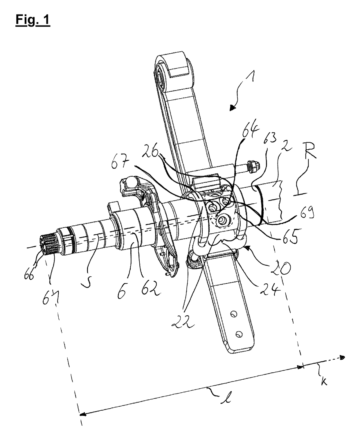
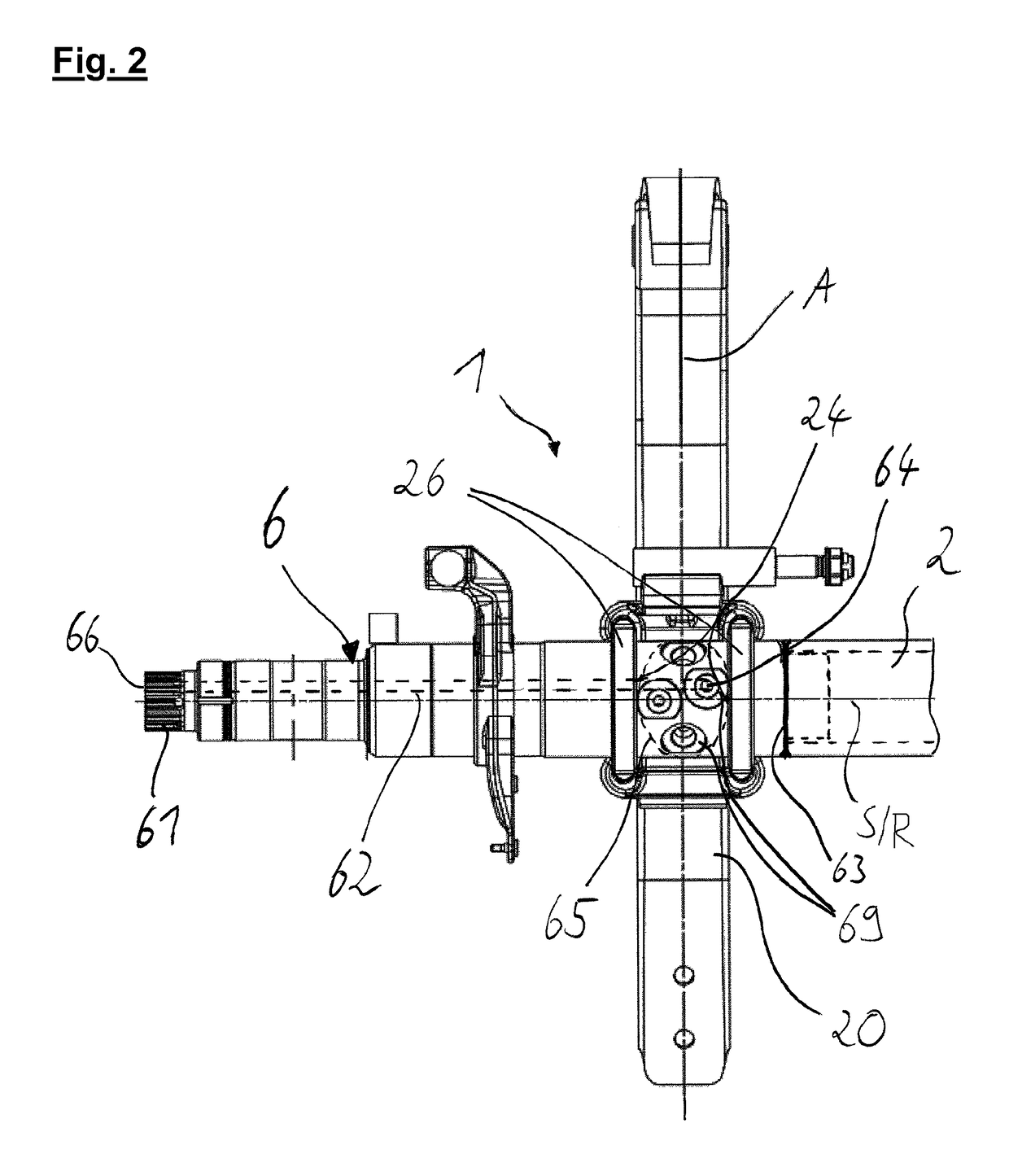
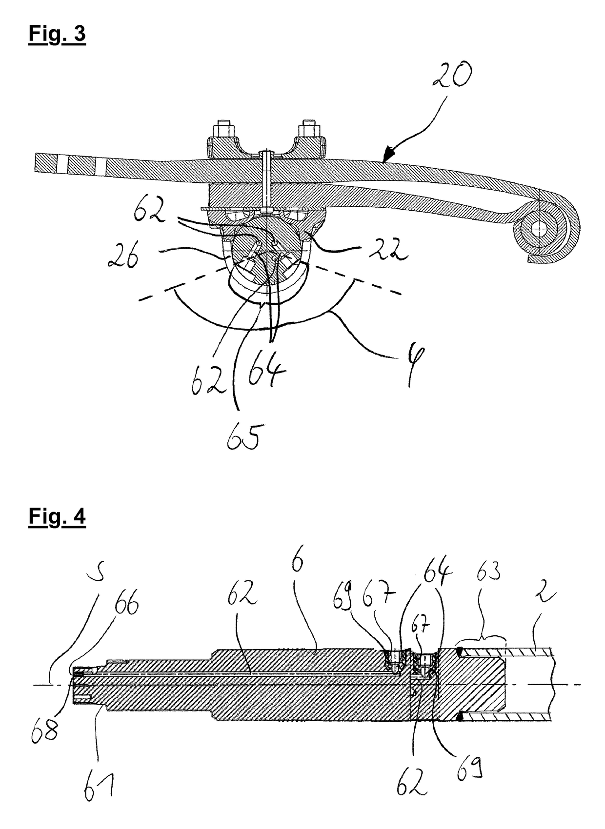
[0023]In the preferred embodiment of FIG. 1, the chassis system 1 comprises a stub axle 6, a suspension arm unit 20 and an axle tube 2 which is preferably secured to the stub axle 6. The stub axle 6 extends substantially along a stub axis S and at least in regions is configured rotationally symmetrically to this stub axis S. The rotationally symmetrical configuration of the stub axle 6 here relates in particular to its outer faces, since preferably at least one longitudinal channel 62 and at least one transverse channel 64 are provided in the interior of the stub axle 6, constituting a deviation from the rotational symmetry. The figure shows (in dotted lines) only one of the longitudinal channels 62 arranged in the stub axle 6. At its end facing away from the axle tube 2 and shown on the left in the figure, the stub axle 6 has a force transmission portion 61. The force transmission portion 61 serves to secure an additional unit (not shown) and to transfer a moment from the additiona...


PUM


Abstract

The present invention concerns an axle unit comprising a stub axle and an axle tube, wherein the stub axle has a longitudinal channel which extends inside the stub axle substantially along a stub axis, wherein the stub axle has a transverse channel which extends inside the stub axle substantially transversely to the stub axis and opens to the environment at the outer face of the stub axle, wherein the longitudinal channel and the transverse channel are connected together, wherein the stub axle has a stub joining region to which the hollow-bodied axle tube can be secured.

Description

BACKGROUND OF THE INVENTION[0001]The present invention concerns an axle unit and a chassis system, in particular for use in trucks.[0002]It has been known from the prior art to mount additional motors, such as for example hydraulic single wheel drives, on axle units in the region of the wheel suspension in order for example to be able to maneuver a trailer when the tractor vehicle is detached, or for example to be able to transmit additional drive power to the individual wheels on steep gradients and / or under heavy load. In the past, a great improvement has already been achieved by integrating in the axle body of a rigid axle the lines necessary to supply the additional drive with the corresponding hydraulic fluid. In this way, already the space required for the axle unit and the space required for the entire chassis system could be reduced, and the hydraulic lines previously arranged outside the axle or axle body could be routed in the shielded areas of the chassis in which no comp...

Claims


Application Information

Patent Timeline
Patent Type & Authority Patents(United States)
IPC IPC(8): F16D65/09B60G11/113B60B35/04B60B35/00B60B35/08B60B35/14B60B35/02B60G9/00B60G7/00
CPCB60G9/003B60B35/02B60B35/04B60B35/08B60B35/14B60G7/001B60G7/008B60G11/113B60B35/007B60G2206/31B60B2310/202B60G2200/31B60G2202/413B60G2204/121B60G2204/148B60G2204/1482B60G2204/201B60G2204/4306B60G2206/012
Inventor CHRIST, ARMINKREINER, KERSTIN
Owner SAF HOLLAND GMBH
Why Eureka
Try Eureka