
Three-rail power supply control system for electrified railway train

a technology of power supply control and electrified railways, applied in the direction of electric energy management, power rails, transportation and packaging, etc., can solve the problems of reducing power density and efficiency, high line cost, and certain safety risks, and achieves low cost, convenient and concise, good economic performance

Pending Publication Date: 2022-03-24
SOUTHWEST JIAOTONG UNIV
View PDF0 Cites 0 Cited by
  • Summary
  • Abstract
  • Description
  • Claims
  • Application Information

AI Technical Summary

Benefits of technology

The present invention provides a three-rail power supply control system for electrified railway trains. By optimizing the power supply mode and structure, the system achieves a lower axle load, increased power density, improved load-carrying efficiency, and better performance. Additionally, the system facilitates unmanned driving and automatic control of train operation through ground power supply. Ground power supply is utilized to reduce costs and ensure power quality in the power grid. The technology is advanced and easy to implement.

Problems solved by technology

Some problems exist here.
The first problem is that the AC-DC-AC traction drive system occupies an absolute weight in the electrical equipment on the main line railway locomotives and motor cars, the weight is high, and the size is large; and due to the high weight, the axle load is increased, the larger the axle load, the higher the line cost, since the size is large, more valuable spaces of locomotives and motor cars are occupied, and then the power density and efficiency are lowered.
The second problem is that intelligent control and automatic train control (ATC) are the only way to replace manual driving.
However, in the case of the current power supply modes of trains, execution equipment required for driving is installed on the trains, and the trains are mobile, even move at high speed, while the commands and structure of automatic train control (ATC) come from a ground control center, the two cannot directly communicate with each other, wireless system communication is required, and wireless system breakdowns or failures will inevitably cause certain safety risks.

Method used


Image

  • Three-rail power supply control system for electrified railway train

Examples


embodiment 1

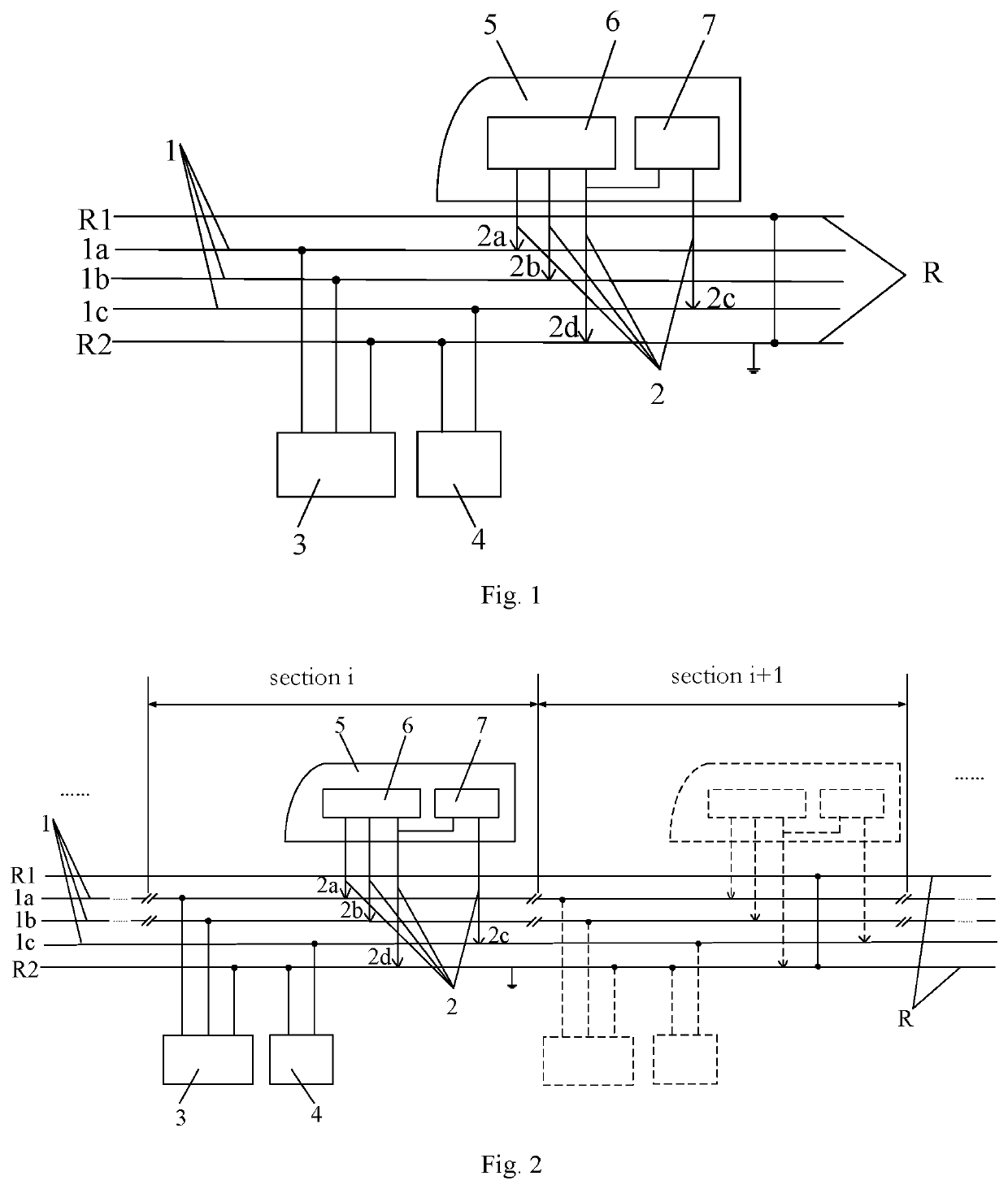
[0021]As shown in FIG. 1, an embodiment of the present invention provides a three-rail power supply control system for electrified railway trains, the system comprises a running rail R along an electrified railway, a power supply rail 1 laid parallel to the running rail R, an AC-DC-AC variable-frequency and variable-voltage device 3 and a rectifying device 4 arranged on the ground, and an on-board current collector 2, a traction motor 6 and auxiliary electric equipment 7 arranged on a train 5; the AC-DC-AC variable-frequency and variable-voltage device 3 and the rectifying device 4 respectively supply power to the traction motor 6 and the auxiliary electric equipment 7 of the train through the power supply rail 1, the running rail R and the on-board current collector 2; the power supply rail 1 comprises a first power supply rail 1a, a second power supply rail 1b and a third power supply rail 1c; the first power supply rail 1a, the second power supply rail 1b and the running rail R f...

embodiment 2

[0027]As shown in FIG. 2, an embodiment of the present invention provides a three-rail power supply control system for electrified railway trains, the system comprises a running rail R along an electrified railway, a power supply rail 1 laid parallel to the running rail R, AC-DC-AC variable-frequency and variable-voltage devices 3 and rectifying devices 4 arranged on the ground, and on-board current collectors 2, traction motors 6 and auxiliary electric equipment 7 arranged on trains 5; the AC-DC-AC variable-frequency and variable-voltage devices 3 and the rectifying devices 4 respectively supply power to the traction motors 6 and the auxiliary electric equipment 7 of the trains through the power supply rail 1, the running rail R and the on-board current collectors 2; the power supply rail 1 comprises a first power supply rail 1a, a second power supply rail 1b and a third power supply rail 1c; the first power supply rail 1a, the second power supply rail 1b and the running rails R fo...


PUM


Abstract

The present invention relates to the technical field of train power supply and operation control, and provides a three-rail power supply control system for an electrical railway train. Power supply rails in the system are divided into a first power supply rail, a second power supply rail, and a third power supply rail, wherein the first power supply rail, the second power supply rail, and a running rail constitute a three-phase AC power supply loop, and the third power supply rail and the running rail constitute a DC power supply loop. An AC-DC-AC variable voltage variable frequency device supplies power to a train traction motor by means of the three-phase AC power supply loop and current collectors. Frequency modulation and voltage regulation power supply is conducted by means of the AC-DC-AC variable voltage variable frequency device on the ground to achieve train driving and operation control. The DC power supply loop is powered by means of a rectifying device on the ground, and power is supplied to auxiliary electric equipment of the train by means of the current collectors. By changing the power supply mode of the system and optimizing the system structure, the weight and axle load of train-mounted equipment are effectively reduced, lightweight of the train is achieved, and the bearing efficiency of the train is improved, and moreover, automatic control and unmanned driving for train operation are achieved in the most economical way.

Description

FIELD OF THE INVENTION[0001]The present invention relates to the technical fields of train power supply and operation control.BACKGROUND OF THE INVENTION[0002]Existing main line electrified railway trains are powered by a power frequency single-phase alternating current (AC) power supply system. Electrical equipment plays an important role on locomotives and motor cars of trains, wherein the most important component is an AC-DC-AC traction drive system. The AC-DC-AC traction drive system is formed by connecting an on-board traction transformer, a traction converter and a traction motor in series, and achieves the purpose of train drive and speed regulation operation by driving the traction motor and changing the speed of the traction motor through frequency regulation and voltage regulation, and the process is called train driving. In reality, train driving is usually done by manual operation, and a few trains are driven automatically. Some problems exist here. The first problem is ...

Claims


Application Information

Patent Timeline
IPC IPC(8): B60L5/39B60L5/36B60M1/30
CPCB60L5/39B60L2200/26B60M1/30B60L5/36B60M3/00B60L5/08Y02T10/72
Inventor LI, QUNZHANGUO, KAIXIE, SHAOFENGLI, ZIHANHUANG, XIAOHONGGUO, YUHUALI, SHUQIANWU, BO
Owner SOUTHWEST JIAOTONG UNIV
Learn More