An electrified railway connecting power supply structure

A technology for electrified railways and structures, applied in the direction of power lines, circuit devices, electrical components, etc., can solve the problems that the impedance value of series reactors cannot be too large, occupy valuable space on trains, and affect system reliability, etc., to eliminate defects impact, reduce the risk of electric shock to personnel, and be easy to implement

Active Publication Date: 2018-10-26
SOUTHWEST JIAOTONG UNIV +1
View PDF1 Cites 0 Cited by
  • Summary
  • Abstract
  • Description
  • Claims
  • Application Information

AI Technical Summary

Problems solved by technology

We have noticed that if the input grid voltage of the traction substation is 110kV and the traction grid adopts 55kV AT power supply mode (transformation ratio = 110 / 55 = 2), using series reactors to increase the impedance of the traction grid will reduce the balanced current in it It is impossible to achieve the desired level (such as below 1%). The reason is that the transformation ratio is too small, and the impedance value of the series reactor cannot be too large due to the limitation of voltage loss. It is attributed to the impedance of the grid side (that is, the impedance of the traction network with the ratio squared) is still not large enough
[0004] At the same time, it is noted that the main circuit of the AC-DC locomotive used in the main line electrified railway is composed of the on-board traction transformer and the AC-DC drive in series. The required low voltage) also has an extremely important function of voltage regulation and speed regulation. However, the production of AC-DC locomotives has long been discontinued. The electric drive is connected in series, but with variable frequency speed regulation, the on-board traction transformer does not need to adjust the voltage, but only has the function of step-down, and the system reliability is affected by the series connection, so the on-board traction transformer takes up valuable space on the train, increases the axle load, and reduces the power. Defects such as density and impact on reliability are becoming more and more apparent, and it is necessary to abandon them

Method used


Image

  • An electrified railway connecting power supply structure
  • An electrified railway connecting power supply structure

Examples


Embodiment

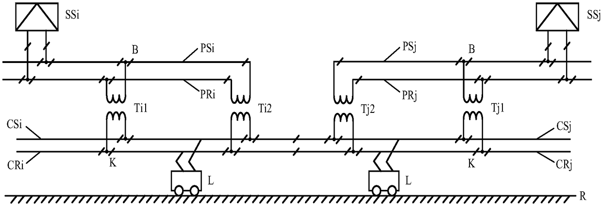
[0020] Example: such as figure 1 As shown, a schematic diagram of the connected power supply structure of an electrified railway. The electrified railway traction power supply system includes two or more main substations. The primary side of the main substations is connected to the same power grid. Note that the two adjacent main substations are the main substation SSi and the main substation SSj, the secondary side of the main substation SSi feeds out the medium-voltage power supply line PSi and the medium-voltage return line PRi, and the medium-voltage power supply line PSi and the medium-voltage return line PRi are connected to the contact power supply line through the step-down transformers Ti1 and Ti2 along the line CSi and contact return line CRi, that is, the two primary terminals of the step-down transformers Ti1 and Ti2 are respectively connected to the medium voltage supply line PSi and the medium voltage return line PRi, and the two terminals of the secondary side a...

example 1

[0028] Example 1: Suppose the voltage of the incoming line grid of the traction substation is 110kV, the traction grid adopts 27.5kV direct supply mode, and the transformation ratio n=110 / 27.5=4, then the balance current (shunt) of the traction grid and the 110kV transmission line in parallel is 1 / 16, if the low-voltage circuit of contacting the power supply line and the contacting return line is added, and its voltage is selected as 5.5kV, then the transformation ratio m=27.5 / 5.5=5, then the balanced current of the low-voltage circuit and the 110kV transmission line in parallel (shunt ) is 1 / (nm) 2 =1 / 4002 = 25 times.

example 2

[0029] Example 2: Suppose the voltage of the incoming power grid of the traction substation is 220kV, the traction network adopts the 27.5kV direct supply mode, and the transformation ratio n=220 / 27.5=8, then the balanced current (shunt) of the traction network and the 220kV transmission line in parallel is 1 / 64, if you add the low-voltage circuit of contacting the power supply line and the contacting return line, and select its voltage as 5.5kV, then the transformation ratio m=27.5 / 5.5=5, then the balanced current of the low-voltage circuit and the 220kV transmission line in parallel (shunt ) is 1 / (nm) 2 =1 / 16002 = 25 times.


PUM


Abstract

The invention discloses a connected power supply structure for an electrified railway, and relates to the technical field of rail transit AC traction power supply. For more than two main substations, the primary side is connected to the same power grid, and the secondary side feeds out the medium-voltage power supply line and the medium-voltage return line; the medium-voltage power supply line and the medium-voltage return line are connected to the Contact power supply lines and contact return lines; medium-voltage power supply lines and medium-voltage return lines, contact power supply lines and contact return lines are all segmented at the step-down transformer; contact power supply lines and contact return lines within the scope of each main substation The voltage phase between the contact return lines is the same; the contact power supply line and the contact return line supply power to the train; under normal circumstances, the medium voltage supply lines and the medium voltage return lines of two adjacent main substations are mutually Not connected, but the adjacent contact power supply lines are connected, and the contact return lines are connected to realize continuous power supply of the train; the middle point of the primary winding of the step-down transformer is pulled out to ground, which can suppress the system overvoltage. Mainly used for rail transit power supply.

Description

technical field [0001] The invention relates to the technical field of single-phase power frequency AC traction power supply for rail transit. Background technique [0002] The main line electrified railway traction power supply system generally adopts single-phase power frequency AC system, and supplies power to the traction load of electric trains through the traction network. In order to distribute the single-phase traction load as evenly as possible in the three-phase power grid, the traction network adopts the scheme of alternating phase sequence and phase-separated and partitioned power supply. The adjacent power supply areas at the phase-splitting partitions are divided by phase-splitting insulators to form electrical split phases, also known as phase splits. Electric split phase is the weakest link of the traction network and the bottleneck of power supply. Electric train passing through electric split phase is the most likely to cause accidents, affecting power sup...

Claims


Application Information

Patent Timeline
Patent Type & Authority Patents(China)
IPC IPC(8): B60M3/00H02J3/00
CPCB60M3/00H02J3/00
Inventor 李群湛
Owner SOUTHWEST JIAOTONG UNIV
Why Eureka
Try Eureka