Fluid pump, cooling system and electrical appliance
a technology of electrical appliances and fluid pumps, applied in the field of fluid pumps, can solve the problems of increasing the number of connecting points, reducing the cooling capacity, and increasing the number of parts and over-all dimensions of the system
- Summary
- Abstract
- Description
- Claims
- Application Information
AI Technical Summary
Benefits of technology
Problems solved by technology
Method used
Image
Examples
first embodiment
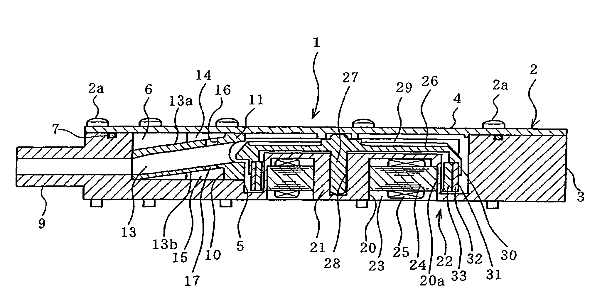
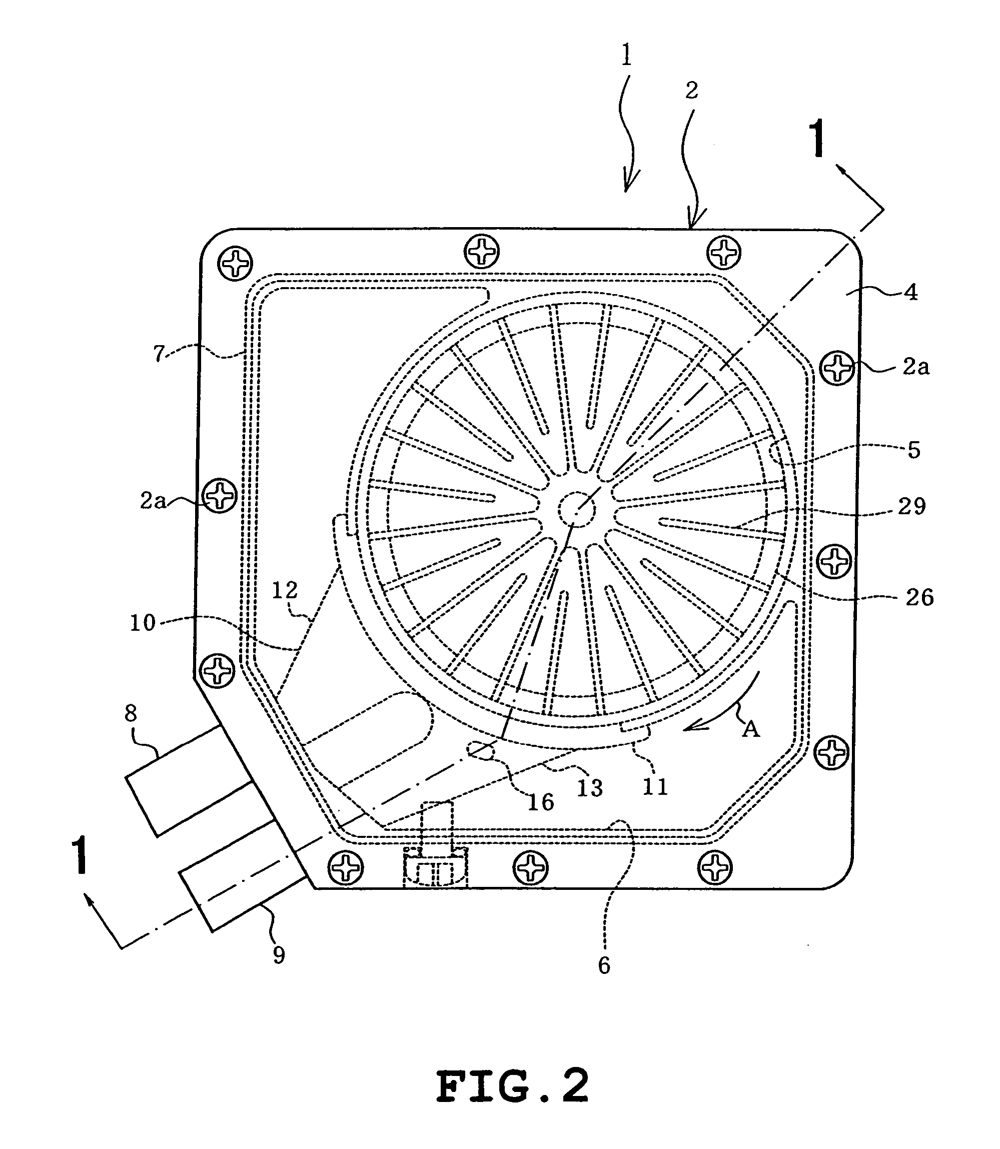
[0032]Referring to FIG. 1 through FIG. 8, the present invention will be described hereunder. FIG. 2 is a plan view showing a fluid pump 1 according to the present invention, while FIG. 1 is a cross sectional view taken along the line 1-1 of FIG. 2, FIG. 3 is an exploded perspective view and FIG. 4 is an exploded perspective view viewed from an opposite direction from FIG. 3, respectively showing the same fluid pump.
[0033]As shown in FIGS. 1 to 4, a case 2 of the fluid pump 1 is of a generally rectangular shape, and includes a case body 3 and a cover 4 attached thereto with a plurality of screws 2a. The case body 3 includes a circular recessed portion with an opening on the side of the cover 4 to concurrently constitute a pump chamber 5, and another similar recess with an opening on the side of the cover 4 that constitutes a reserve tank 6. The opening of the pump chamber 5 and the reserve tank 6 are closed by the cover 4. Between the case body 3 and the cover 4, a sealing member 7 s...
third embodiment
[0057]In the cooling system 50 also, the fluid pump 1 includes therein the reserve tank 6, which eliminates the need to additionally install a reserve tank. This allows avoiding an increase in the number of parts and keeping the cooling system 50 from becoming oversized, and further decreasing the number of connection points.
[0058]Now FIGS. 11 through 15 show a cooling system according to a fourth embodiment of the present invention, which is different from the first embodiment in the following aspect.
[0059]A fluid pump 60 is provided with a different number of liquid inlets at different positions from the fluid pump 1 of the first embodiment. Referring to FIG. 12, the case body 3 of the case 2 is provided with a first liquid inlet 61 communicating with the reserve tank 6 and a second liquid inlet 62 communicating with the pump chamber 5, which are located on a side wall on the upper face of the case body 3.
[0060]The first liquid inlet 61 is provided so as to communicate in and out...
fourth embodiment
[0066]The arrangement as the fourth embodiment provides the following advantageous effects in particular. The case 2 of the fluid pump 60 is provided with the first liquid inlet 61 communicating with the inside of the reserve tank 6 and the second liquid inlet 62 communicating with the inside of the pump chamber 5. Accordingly, when introducing a liquid through the first liquid inlet 61, air remaining in the pump chamber 5 and in the fluid path communicating therewith can be efficiently discharged outward through the second liquid inlet 62 communicating with the pump chamber 5, and air present in the reserve tank 6 can be easily discharged outward through the first liquid inlet 61.
[0067]If, for example, only the first liquid inlet 61 were provided, without the second liquid inlet 62, the air remaining in the pump chamber 5 and in the fluid path communicating therewith would not be discharged until it is finally discharged through the first liquid inlet 61 after having been led into ...
PUM
 Abstract
Description
Claims
Application Information
 - R&D
- Intellectual Property
- Life Sciences
- Materials
- Tech Scout
- Unparalleled Data Quality
- Higher Quality Content
- 60% Fewer Hallucinations
Browse by: Latest US Patents, China's latest patents, Technical Efficacy Thesaurus, Application Domain, Technology Topic, Popular Technical Reports.
© 2025 PatSnap. All rights reserved.Legal|Privacy policy|Modern Slavery Act Transparency Statement|Sitemap|About US| Contact US: help@patsnap.com


