Coaxial connector and coaxial cable connector assembly and related method

a technology of coaxial cable and connector, which is applied in the direction of insulating conductor/cable, connection formation by deformation, coupling device connection, etc., can solve the problems of poor crimping, low reliability of crimping, and poor electrical connection, so as to achieve sufficient retention and reduce the effect of time, labor and material costs

Active Publication Date: 2008-05-13
PPC BROADBAND INC
View PDF16 Cites 65 Cited by
  • Summary
  • Abstract
  • Description
  • Claims
  • Application Information

AI Technical Summary

Benefits of technology

[0011]The connectors disclosed herein are comprised of a small number of components that can be installed on a coaxial connector cable in an extremely efficient manner in terms of time, labor, and material costs. Additionally, such connectors are easy to use as a cable termination, such as when applied as in a connector / cable assembly such as a jumper assembly, while providing provide necessary signal shielding and sufficient retention on the coaxial cable. The method of installing the connector onto coaxial cable permits flexibility and interchangeability during assembly, where, for example, various types and / or sizes of couplers can be matched with various shells and / or posts, which would not otherwise be available with connectors that require pre-assembly before attachment to a cable.

Problems solved by technology

However, crimping braided outer conductors can present some difficulties.
Usually, the braid is captured in a layer between a tubular outer ferrule and the connector body, wherein the outer ferrule is crimped onto the crimp sleeve which in turn is radially compressed into engagement with the cable, but such crimps are not typically considered to be highly reliable, because, for example, there are typically large voids in the interface allowing for corrosive degradation of the contact surfaces, and / or the mechanical pull strength to the joint does not approach the strength of the wire.
Additionally, such a crimp connection typically allows relative movement between all three components, which results in a very poor, noisy electrical connection.
While standardized cable preparation tooling and connector actuation tooling has increased flexibility and interchangeability in field installations where an installer is concerned with making cable connection using one or a few connectors at a particular location, the implementation of these standardized connector and tooling systems for the manufacture of cable assemblies such as CATV jumper cables in large quantities tends to limit the efficiency of mass assembly of the jumpers, thereby causing unnecessary expense to be incurred in the manufacture of the assemblies.
However, couplers are typically provided in standard sizes, and, for given standard coupler sizes, practical limits exist on reducing the outer diameter of the body of known connectors (for example because such connectors need to be able to receive the folded back braid of the cable and need to be able to clamp onto the cable, the outside diameter of the body needs to be large enough to structurally accommodate those features), so limitations exist on the flexibility of increasing the difference in outer diameter E1 in known connectors, used in conjunction with known cable preparation methods.

Method used


Image

  • Coaxial connector and coaxial cable connector assembly and related method
  • Coaxial connector and coaxial cable connector assembly and related method
  • Coaxial connector and coaxial cable connector assembly and related method

Examples


Embodiment Construction

[0031]Reference will now be made in detail to the present preferred embodiment(s) of the invention, examples of which are illustrated in the accompanying drawings. Whenever possible, the same reference numerals will be used throughout the drawings to refer to the same or like parts.

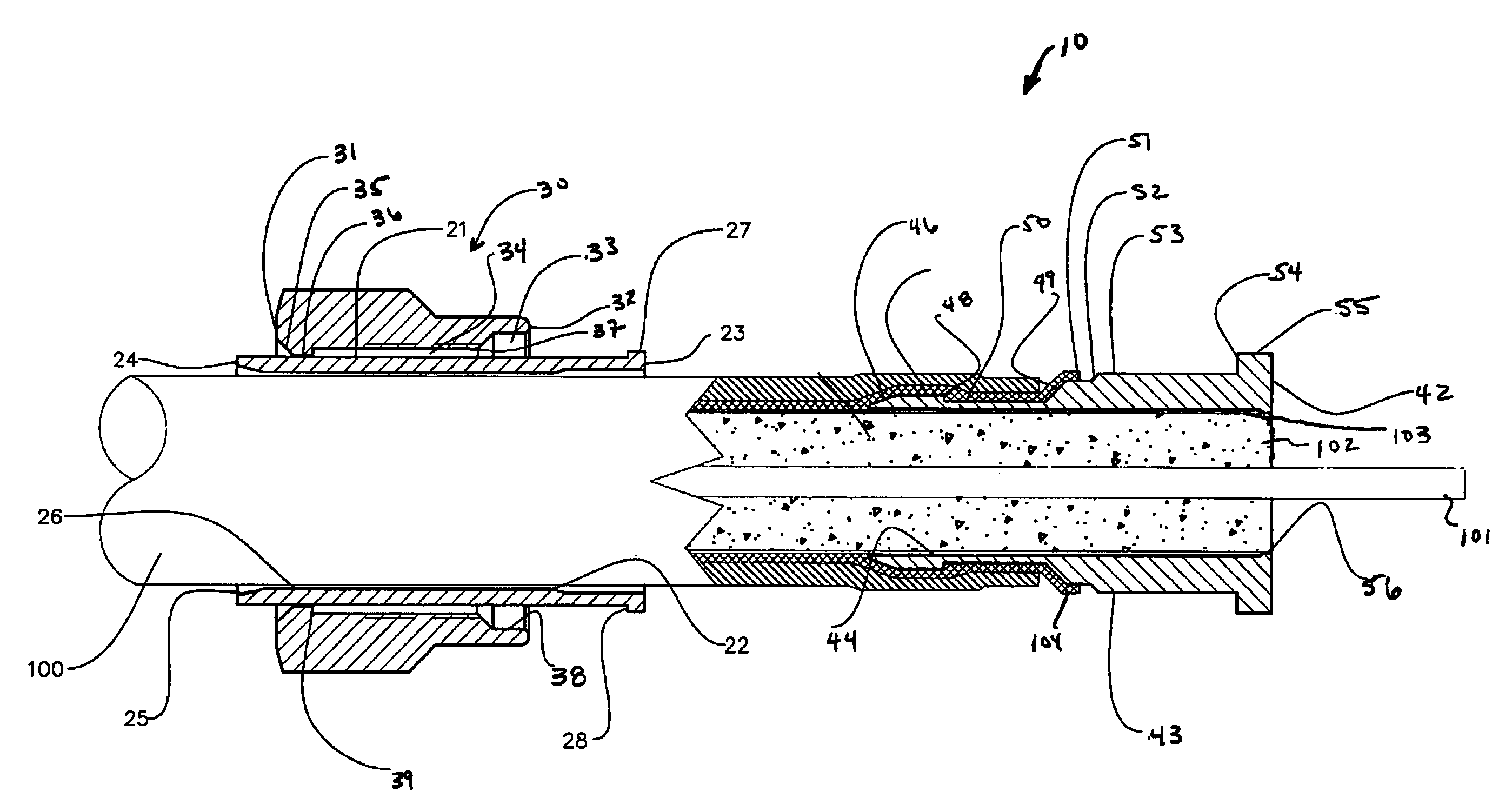
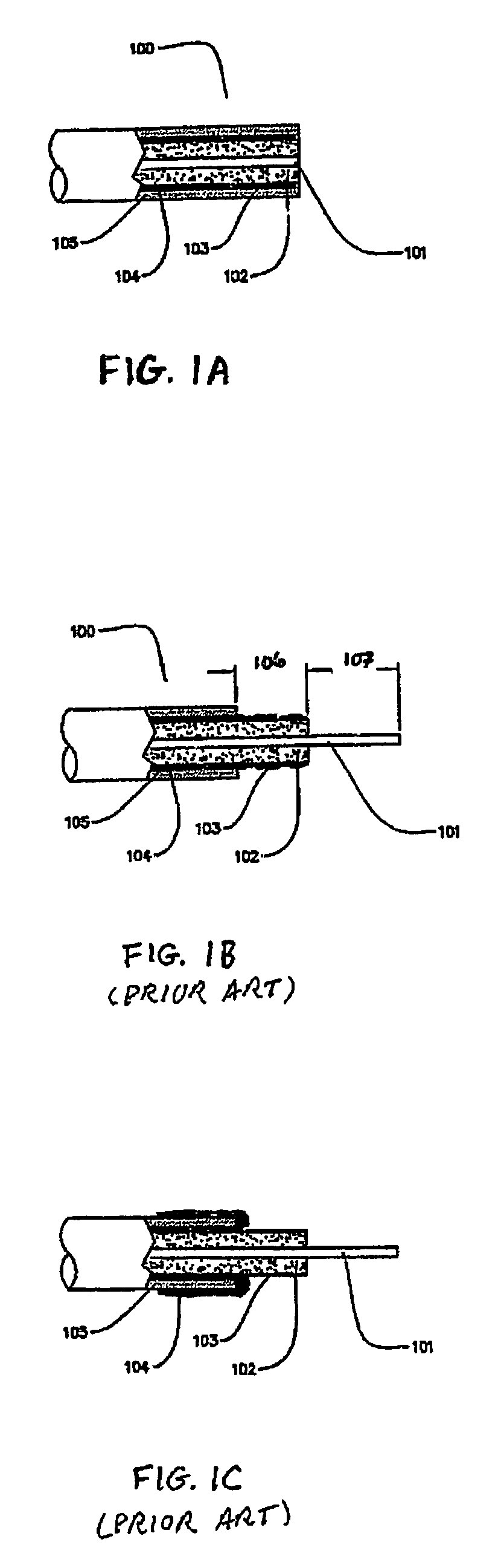
[0032]FIGS. 3A-3C are partial cutaway views along the centerline of a coaxial cable illustrating the cable preparation method as disclosed herein. FIG. 3A shows cable 100 comprising center conductor 101, dielectric 102, outer conductor or shield 103, braid 104, and jacket 105. For some embodiments, such as a coaxial cable jumper, a desired length of cable 100 is cut, preferably making a clean cut. Referring to FIG. 3B with a desired length of cable 100, the cable preparation includes removing a portion of the protective layer 105, a portion of the braid 104, and a portion of the dielectric 102 from the end of the coaxial cable to provide a prepared end of the cable, which can be effected using one or more...


PUM

PropertyMeasurementUnit
axial movementaaaaaaaaaa
movementaaaaaaaaaa
mechanical contactaaaaaaaaaa

Abstract

A method of making a coaxial cable assembly is disclosed, the assembly comprising a coaxial cable and a connector, or connector termination, on at least one end of the cable. A connector, comprised of connector components, is also disclosed. The method comprises placing connector components into contact with the cable before the connector components are assembled into a connector. The connector is assembled simultaneously with securing the connector to the cable to make a coaxial cable assembly. A method of preparing coaxial cable in a manner suitable for making coaxial cable assemblies is also disclosed. The coaxial cable assembly can be a jumper, or a lead.

Description

BACKGROUND OF THE INVENTION[0001]1. Field of the Invention[0002]The present invention relates generally to coaxial cable connectors and coaxial cable / connector assemblies, and particularly to coaxial cable connectors suitable for coaxial assemblies.[0003]2. Technical Background[0004]Coaxial cable connectors such as F-connectors are used to attach coaxial cable to another object such as an appliance or junction having a terminal adapted to engage the connector. F-connectors are often used in conjunction with a length of coaxial cable to create a jumper cable assembly to interconnect components of a cable television system. A jumper typically has one coaxial connector (connector termination) at each end of the length of cable. The coaxial cable typically includes a center conductor, or inner conductor, surrounded by a plurality of outer cable components, for example the inner conductor is surrounded by a dielectric, in turn surrounded by one or more outer conductive layers, or metalli...

Claims


Application Information

Patent Timeline
Patent Type & Authority Patents(United States)
IPC IPC(8): H01R9/05
CPCH01R9/0524H01R13/5045H01R13/622Y10T29/49174Y10T29/49181Y10T29/49218Y10T29/49123
Inventor BURRIS, DONALD ANDREWLUTZ, WILLIAM BERNARDWOOD, KENNETH STEVEN
Owner PPC BROADBAND INC
Why Eureka
Try Eureka