
Motor coil-shorting detecting unit

a detection unit and motor coil technology, applied in the field of electric machines, can solve the problems of excessive current in the shorted turn, affecting the operation of the motor coil, etc., and affecting the reliability of future performance. , it is difficult to use normal approaches to shorted turn protection in fault-tolerant electrical machines

Inactive Publication Date: 2008-05-13
ROLLS ROYCE PLC
View PDF7 Cites 7 Cited by
  • Summary
  • Abstract
  • Description
  • Claims
  • Application Information

AI Technical Summary

Benefits of technology

[0006]In accordance with the present invention, there is provided an electrical machine comprising a plurality of coils associated with an armature to provide a plurality of phases of operation upon relative rotation between the coils and a rotor, detection means for an electrical short circuit in at least one of said coils to determine a faulted turn and electrical current injection means whereby when an electrical short circuit is detected in the faulted turn, then an appropriate electrical current is injected into that coil to effectively protect that coil or part of that coil subject to an electrical short circuit in order to inhibit excessive electrical current flow through the faulted turn of the coil or other part of the coil.

Problems solved by technology

If recognition and short circuiting is not so performed, then the electrical current in the shorted turns will be excessively high and could jeopardise the entire winding immediately or compromise its reliability for future performance.
Nevertheless, where there are few turns per winding coil, it will be appreciated that it may be difficult to use normal approaches to shorted turn protection in a fault tolerant electrical machine.

Method used


Image

  • Motor coil-shorting detecting unit
  • Motor coil-shorting detecting unit
  • Motor coil-shorting detecting unit

Examples


Embodiment Construction

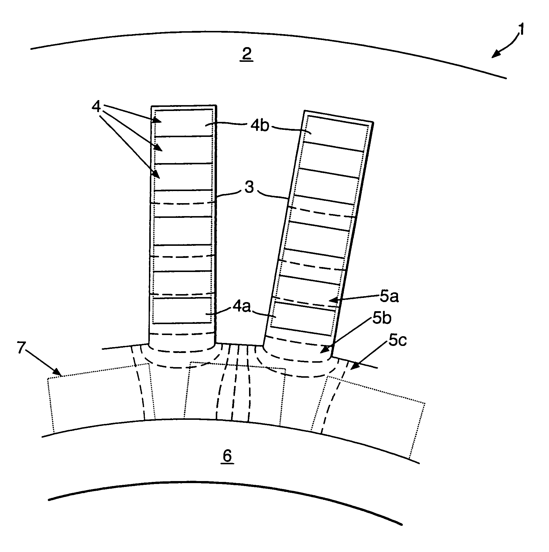
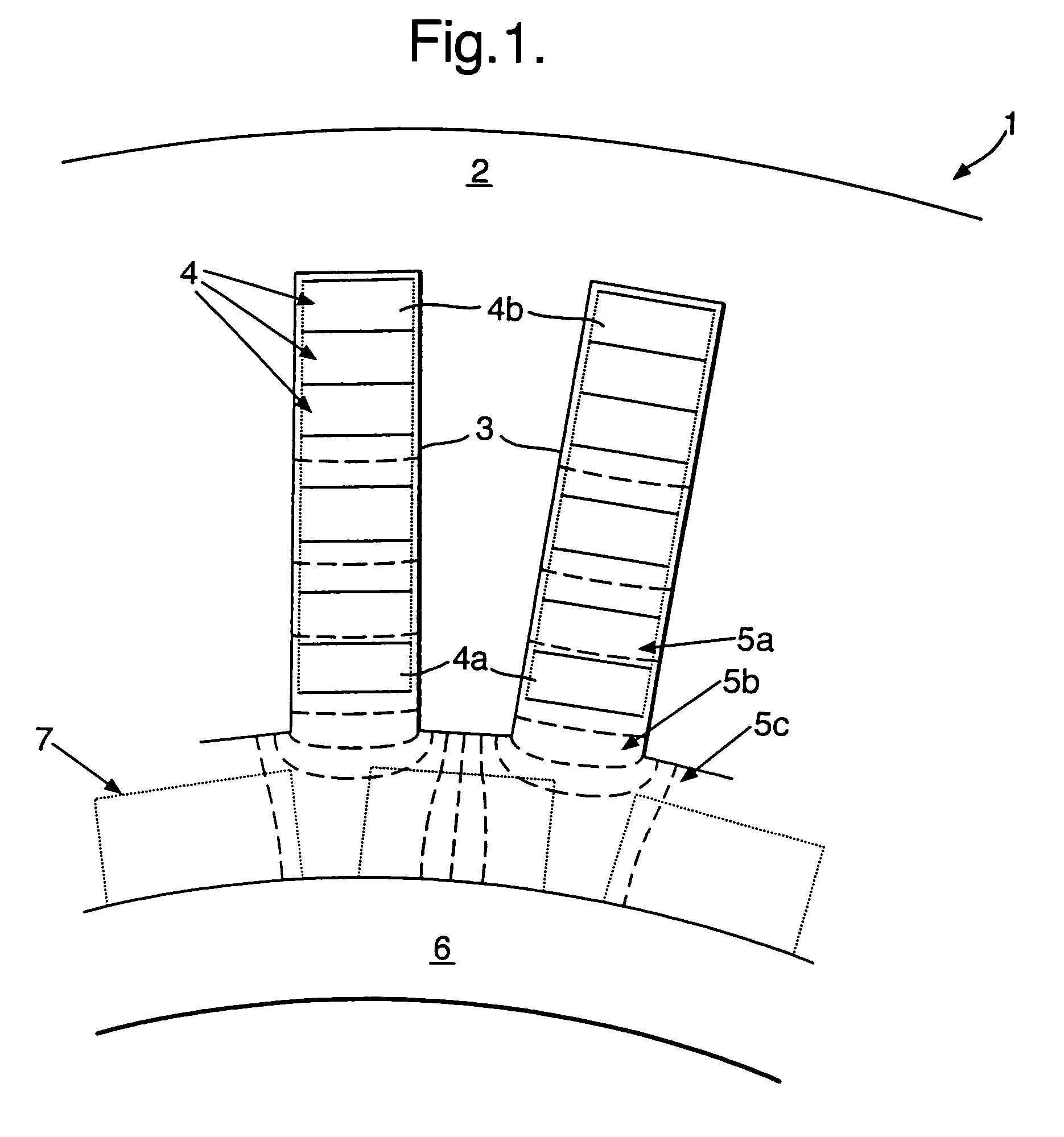
[0016]Referring to FIG. 1 providing a schematic cross-section of part of an electrical machine 1 in accordance with the present invention. Thus, the electrical machine 1 comprises a stator core 2 within which slots 3 are provided to accommodate coils 4 in the form of respective turns of rectangular section conductor usually, but not necessarily provided by drawn copper bars. The slots 3 are shown as open which is consistent with having a stiff bar coils 4 but it will also be understood that semi-closed slots could be provided within which the coils 4 are located. In FIG. 1, broken lines 5 illustrate magnetic flux paths which contribute to armature winding reactance. Thus, line 5a relates to armature slot leakage flux, line 5b relates to tooth leakage flux and line 5c relates to air gap flux across from the armature coil to a rotor 6 incorporating permanent magnets 7. It will be appreciated by appropriate phase flow of electrical current through the coil windings 4 and consequent mag...


PUM


Abstract

In order to be acceptable for safety critical applications, it is necessary for an electrical machine to allow continued operation despite an electrical short circuit in one of the operational phases of that electrical machine. It will be appreciated that an electrical short circuit creates excessive electrical current through the short circuit with significant heating and other detrimental effects. However, the electrical machine can operate with one operational phase disabled. In such circumstances, the present invention incorporates means for determining an electrical short circuit has occurred and then injects an electrical current approximately equal to or greater than the rated electrical current. In such circumstances, the operational phase or coil 4, 24, 34 is effectively protected despite the electrical short circuit and hence the electrical machine can continue to operate.

Description

[0001]This is a continuation of International Appln. No. designating the U.S. PCT / GB2004 / 002601 filed Jun. 18, 2004.FIELD OF THE INVENTION [0002]The present invention relates to electrical machines and more particularly to protection against damage arising from shorted turns on coils in such machines.BACKGROUND OF THE INVENTION [0003]Permanent magnet electrical machines whether used as motors or generators are relied upon in safety critical situations. Thus, the electrical machine must continue to operate despite shorted turns or coils in the armature winding of the machine. Typically, these permanent magnet electrical machines have modular windings in which there is physical and electromagnetic separation of coils wound around alternate armature teeth. It is this separation of the armature coils which leads to the term modular winding. For truly fault tolerant electrical machines, there is a general requirement for an armature reactance of around 1.0 per unit and so this requires a...

Claims


Application Information

Patent Timeline
IPC IPC(8): F21V7/04H02H5/04H02H7/08H02K11/00H02P29/02
CPCH02K11/001H02P29/02H02P29/022H02K11/20H02P29/032
Inventor CULLEN, JOHN J AANTONOPOULOS, GEORGE
Owner ROLLS ROYCE PLC
Learn More