High capacity and high efficiency filter deck assembly

a filter deck and high efficiency technology, applied in the direction of moving filtering element filters, filtration separation, separation processes, etc., can solve the problems of loss of pressure differential in that area, loss of drainage in the area corresponding to the seal member, etc., to achieve effective prevention of pulp sheet rewetting, improved filtering effect, and greater drainage surface

Inactive Publication Date: 2008-05-20
ANDRITZ INC
View PDF7 Cites 9 Cited by
  • Summary
  • Abstract
  • Description
  • Claims
  • Application Information

AI Technical Summary

Benefits of technology

[0006]Unlike the deck assemblies known to date, the present inventive technology provides a filter deck assembly for a rotary drum filter that has a greater drainage surface, a more efficient filtering action, and is constructed and arranged to permit thermal expansion of the component elements without resultant damage. Furthermore, the present inventive technology provides a filter deck assembly that effectively prevents rewetting of the pulp sheet from a run back of the filtrate as the drum rotates through the descending path of the cycle. The present inventive technology also provides a filter deck assembly that is durable and has a long commercial life. Finally, the present inventive technology provides a filter deck assembly that is particularly constructed and arranged to allow simple and quick replacement of filter deck assembly sections.
[0007]The foregoing advantages are obtained in a rotary drum filter having a plurality of longitudinally and radially extending division grids mounted about the outer circumference of a drum. A plurality of corrugated sheets for drainage decks are provided, with the leading and trailing edges of each sheet mounted on circumferentially adjacent pairs of division grids to define filtrate compartments. An equivalent number of perforated filter decks or plates are also provided. Each filter deck or plate is attached to the top of a corrugated sheet (drainage deck) and has a leading edge that is set back from the leading edge of the attached corrugated sheet. An equivalent number of perforated cap strips (longitudinal cap strips) are attached to the tops of the division grids to keep the filter deck assemblies within their proper locations and ranges of movement, to allow maximum drainage and to allow ease of replacement of cap strips and filter deck assemblies.
[0008]A seal member is positioned in front of (partially or wholly) and / or underneath the leading edge, or in close proximity thereto, of each corrugated sheet (drainage deck). A seal clip is positioned and attached in front of and / or underneath the leading edge of each corrugated sheet and holds the seal member in place. The seal clip can be tack-welded or spot welded to the corrugated sheet, for example, and depending on the geometry, to the front and / or bottom of the corrugated sheet. When the seal member is positioned in front of and / or underneath the corrugated sheet, the seal member may be configured in a manner so that all or a portion of the seal member is located or pinched between the seal clip and the leading edge, or near the leading edge, of the corrugated sheet. The seal member is a compressible material that acts in conjunction with the seal clip to, among other things, seal the leading edge area of the drainage deck when the corresponding portion of the rotary drum is descending. It also assists with and maximizes the filter deck drainage area and deck pressure differential in the area of the seal clip.
[0009]Some of the problems with the prior art devices are the loss of drainage in the area corresponding to the seal member and the loss of pressure differential in that area. For example, the L-shaped seal member of U.S. Pat. No. 4,906,364 results in the loss of drainage in the area of the seal member and the loss of pressure differential in that area. The loss of drainage and pressure differential is detrimental to the capacity of the rotary drum filter and degrades washing efficiency. The present inventive technology provides additional drainage capacity and improved washing efficiency.

Problems solved by technology

Some of the problems with the prior art devices are the loss of drainage in the area corresponding to the seal member and the loss of pressure differential in that area.
For example, the L-shaped seal member of U.S. Pat. No. 4,906,364 results in the loss of drainage in the area of the seal member and the loss of pressure differential in that area.
The loss of drainage and pressure differential is detrimental to the capacity of the rotary drum filter and degrades washing efficiency.

Method used


Image

  • High capacity and high efficiency filter deck assembly
  • High capacity and high efficiency filter deck assembly
  • High capacity and high efficiency filter deck assembly

Examples


Embodiment Construction

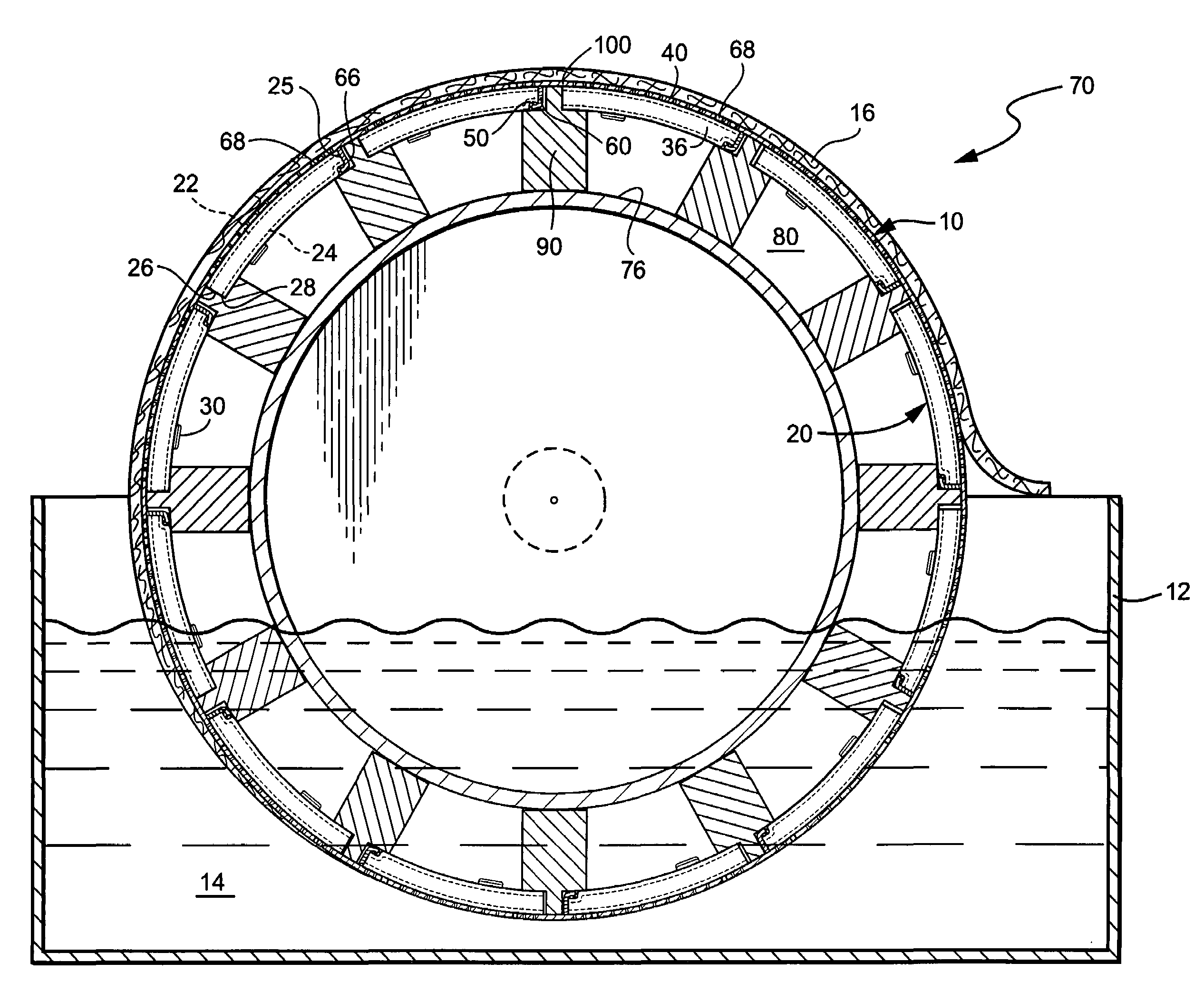
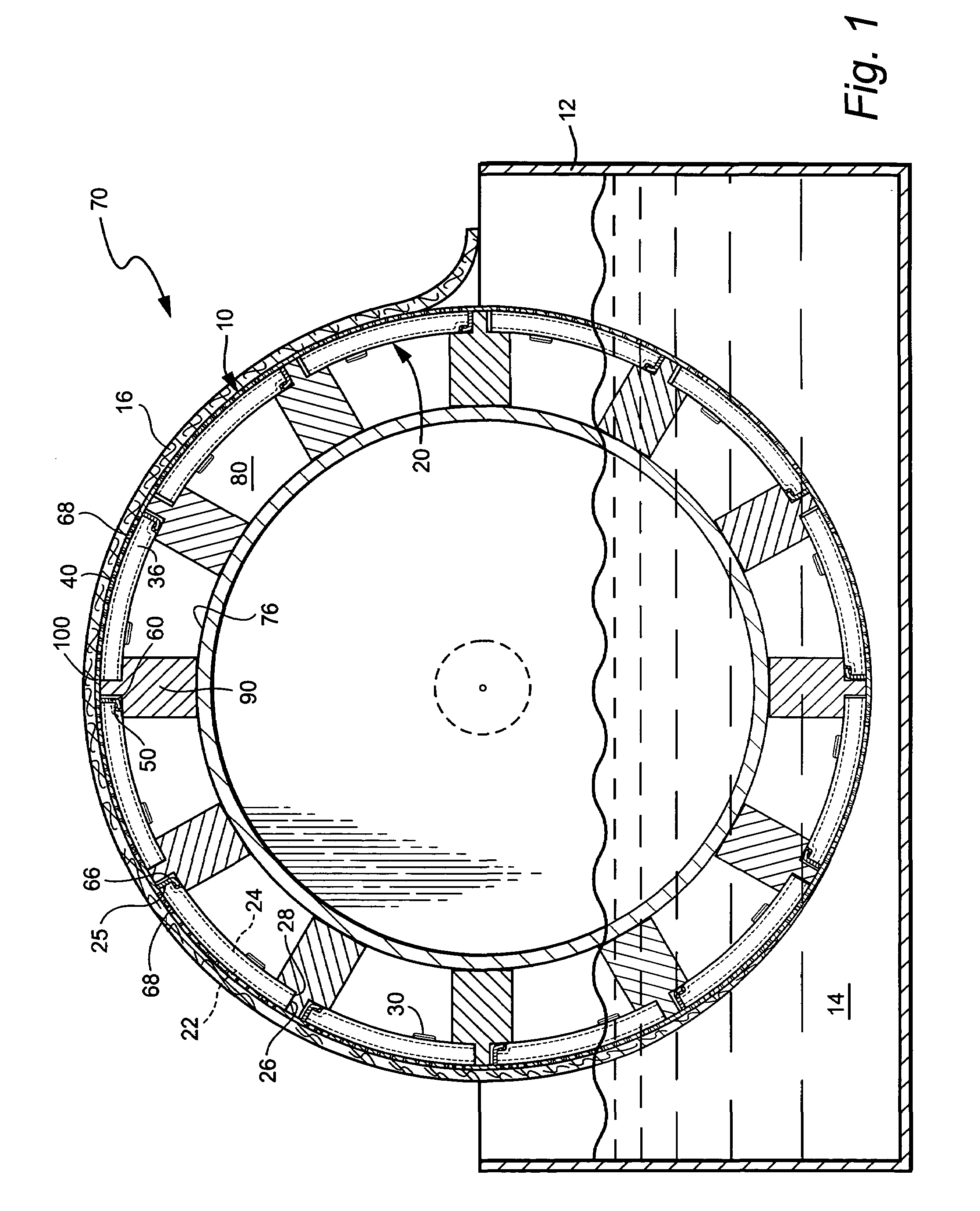
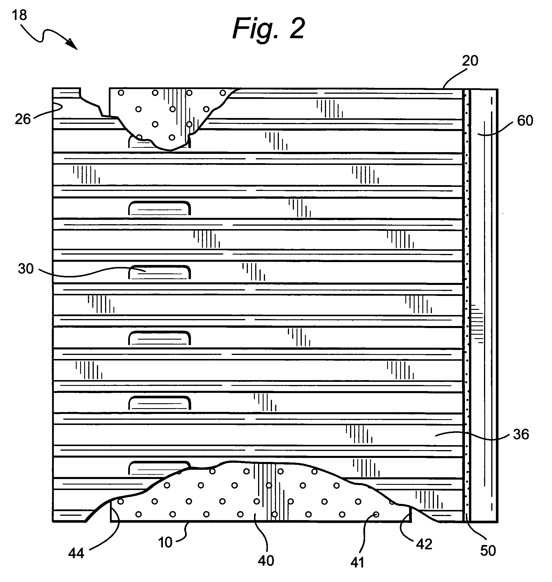
[0028]The accompanying FIGURES schematically depict filter drums, filter deck assemblies, and configurations of filter deck assemblies, cap strips and grids that are exemplary, illustrative, non-limiting arrangements embodying the present inventive technology, including the method of use and replacement.

[0029]Referring now to the drawings, wherein similar referenced characters designate corresponding parts throughout the several views, the rotary drum filtering apparatus illustrated in FIGS. 1 and 2 comprises a drum structure, generally designated as 70, that is, at the user's place of business, at least partially submerged in a tank 12 that contains a pulp stock 14 or other slurry to be filtered. The drum is constructed in a conventional manner so that a pressure or vacuum is applied to drain filtrate and create a pulp sheet 16 on a filter deck assembly 18. For example, the pressure differential is created by the filtrate being atmospheric pressure and the drum being contained in a...


PUM

PropertyMeasurementUnit
temperatureaaaaaaaaaa
pressureaaaaaaaaaa
lengthaaaaaaaaaa

Abstract

A rotary drum filter has a plurality of longitudinally extending division grids mounted about the outer circumference of a drum. A plurality of corrugated sheets are provided, with the leading and trailing edges of each sheet mounted to circumferentially adjacent pairs of division grids to define filtrate compartments. An equivalent number of perforated filter plates are also provided. Each filter plate is attached to the top of a corrugated sheet and has a leading edge and a trailing edge that are set back from the leading edge and trailing edge of the corrugated sheet. A seal clip is positioned near the leading edge of each corrugated sheet. A seal member or seal members is / are held in place by the seal clip and is / are positioned at the face of the leading edge of each corrugated sheet or beneath and near the face or each corrugated sheet. A perforated cap strip can be removably attached to the top of each division grid to thereby retain for confined movement each filter plate and corrugated sheet combination (filter deck and drainage deck) during rotary drum filter operation and to allow easy replacement of the filter plate and corrugated sheet combination(s) and / or cap strip(s) when the rotary drum filter is not in operation. This rotary drum filter design and operation has increased capacity and efficiency.

Description

FIELD OF TECHNOLOGY[0001]The present invention relates generally to a filter deck assembly and its method of use and replacement. In particular, the present invention relates to a specially designed, constructed, utilized and replaceable high capacity and high efficiency filter deck assembly for a rotary drum filter.BACKGROUND AND SUMMARY OF TECHNOLOGY[0002]Rotary drum filters are well known and are used in the pulp and paper industry to filter and wash pulp slurries, for example, from U.S. Pat. Nos. 4,808,265 and 4,906,364 (the entire contents of which are expressly incorporated hereinto by reference). Rotary drum filters generally comprise a cylindrical drum mounted for rotation in a tank containing a slurry solution. A filter deck assembly is mounted radially outward of the surface of the drum. As the drum is rotated, a low pressure is maintained inside the drum so that a pulp sheet is formed on the surface of the filter deck assembly. The filter deck assembly functions to space ...

Claims


Application Information

Patent Timeline
Patent Type & Authority Patents(United States)
IPC IPC(8): B01D33/073B01D33/067B01D33/06B01D33/44D21D5/06D21D5/14
CPCB01D33/067B01D33/09
Inventor GRACE, TODD S.GOTTBERG, JOSEPH A.
Owner ANDRITZ INC
Why Eureka
Try Eureka