Machine track roller assembly

a track roller and machine technology, applied in the field of track rollers, can solve the problems of disproportionate load on the track roller, difficulty in achieving sufficient traction of the conventional tire, so as to reduce side and edge load

Active Publication Date: 2008-05-20
CATERPILLAR INC
View PDF16 Cites 31 Cited by
  • Summary
  • Abstract
  • Description
  • Claims
  • Application Information

AI Technical Summary

Benefits of technology

[0011]In still another aspect, the present disclosure provides a method of reducing side and edge loading of a track roller bearing in a track-type work machine. The method includes the step of transmitting selected loads on the bearing toward a center thereof at least in part by crowning at least one rotatable sleeve of the bearing.

Problems solved by technology

“Tracks” rather than wheels are typically used on work machines operating in environments where creating sufficient traction with conventional tires is problematic or impossible.
Work machines often operate in particularly rugged environments, including bedrock, refuse mounds, gravel, and uneven soil or other types of terrain.
As the work machine traverses rough or uneven ground, or turns on a rugged work surface, the track rollers can be subjected to substantial loads.
Despite relatively rugged designs, when the work machine track rollers encounter certain loads, various of the components, or regions thereof, may disproportionately bear much of the load on the track roller.
In such cases, a deflection of the rim relative to the shaft has a tendency to impinge upon an outside edge portion of the sleeve bearing that supports the track roller.
Damage or excessive wear of the sleeves and other components can result over time, and / or frequent servicing may be required.
A degree of wobble in the sleeve, due to large clearances, and robust bearing components, can prolong the service life of certain of the components.
One drawback to many prior art designs, however, is that it is generally necessary to align the track roller rim portions to fairly exacting specifications.
Even small misalignments between adjacent track roller rim portions can affect the performance of the bearing assembly and bearing seals.
Because a common shaft typically extends through both roller rim portions, misalignment between the respective bores has a tendency to cause misalignment between the rim portions and the shaft.
In other words, even small misalignments between the bores can cause the respective shaft and bore axes to be out of alignment.
Consequently, rotation of the roller, and in particular, uneven loads on the roller can cause edge portions of the sleeves to bear a disproportionate part of the load and wear.
Thus, unless the components are manufactured and assembled with relatively close tolerances, edge loading of the bearing can eventually result in premature failure.
Other problems with known designs relate to the relatively large size of the bore passing through the track roller rim portions, in particular the challenge in effectively sealing the bore to retain lubricating oil therein.
A larger bore diameter may require more complex, and less reliable sealing.
Not only is the design thus relatively complicated, but additional bores for the retainers are required in the rim.
The combination of large clearances between bearing sleeves and shafts, and additional bores for the retainers consumes a significant amount of the rim volume.
Over the course of many working hours, a portion of the rim volume wears away.
Reducing this available wear volume in many designs contributes to the requirement of unduly frequent replacement.

Method used


Image

  • Machine track roller assembly
  • Machine track roller assembly
  • Machine track roller assembly

Examples


Embodiment Construction

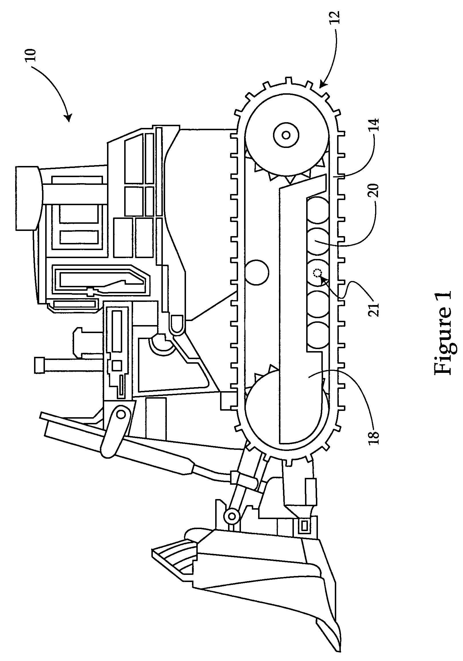
[0017]Referring to FIG. 1, there is shown a work machine 10 having a roller frame 18 and a track assembly 12 including a track 14. Work machine 10 might be any of a wide variety of track type work machines including, for example, a bulldozer, an agricultural tractor, a crane, a military vehicle, etc. A plurality of rollers 20 are positioned adjacent the bottom, or ground engaging side, of track assembly 13 and are rotatable against an inside of track 14. In a preferred embodiment, each of track rollers 20 is rotatably supported on a bearing assembly 21, as described herein, that is operable to transmit selected loads on each of rollers 20 toward a center of the respective bearing assembly 21.

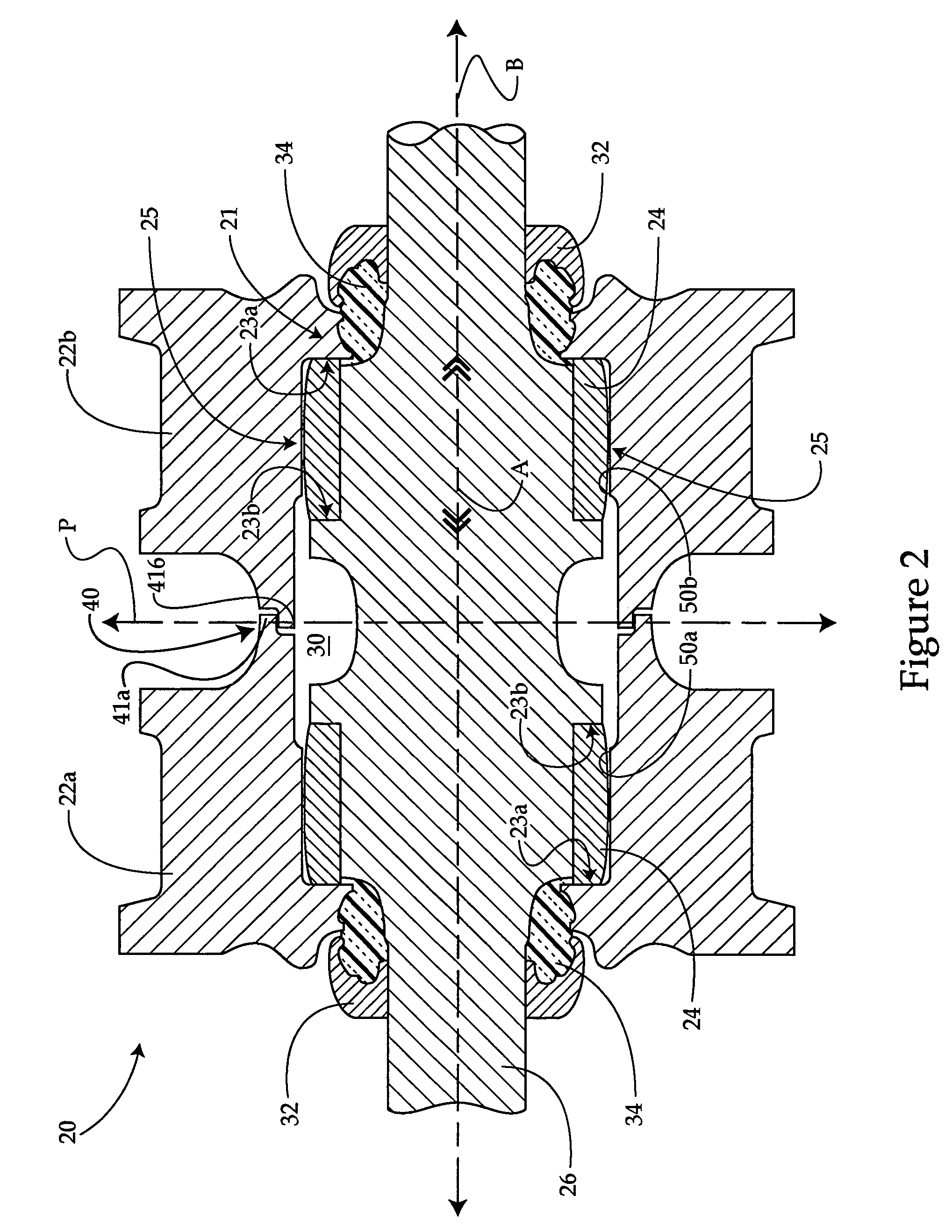
[0018]Referring also to FIG. 2, there is shown a front sectioned diagrammatic view of a track roller 20 suitable for use with work machine 10. Roller 20 preferably includes first and second adjacent rim portions 22a and 22b, respectively. Rim portions 22a and 22b are preferably joined at a weld ...


PUM


Abstract

A track-type work machine is provided, including a roller frame and a track extending about the roller frame. A track roller is mounted along the roller frame and rotatable against the track. The track roller is rotatably supported by a bearing that includes a shaft extending in the track roller and at least one sleeve rotatable about the shaft. At least one of the sleeve and the track roller include a load transmitting crown. A method is further provided of reducing edge loading of a track roller bearing, by transmitting selected loads on the bearing toward a center thereof at least in part by crowning a rotatable sleeve of the bearing.

Description

TECHNICAL FIELD[0001]The present disclosure relates generally to track-type work machines, and relates more particularly to track rollers for track-type work machines.BACKGROUND[0002]Track-type work machines are in widespread use in construction, mining, forestry and similar industries. Bulldozers, cranes and large agricultural tractors are familiar track-type work machines along roads, freeways and at construction sites. “Tracks” rather than wheels are typically used on work machines operating in environments where creating sufficient traction with conventional tires is problematic or impossible. Rather than rolling across a work surface on wheels, track-type work machines utilize one or more tracks extending about a plurality of rotating components. Such tracks are typically made up of a loop of coupled metal links having outer sides that engage the ground or work surface, and inner sides traveling about the rotating components, which can include various drive sprockets, tensioner...

Claims


Application Information

Patent Timeline
Patent Type & Authority Patents(United States)
IPC IPC(8): B62D55/14
CPCB62D55/15F16C23/041
Inventor OERTLEY, THOMAS E.
Owner CATERPILLAR INC
Why Eureka
Try Eureka