Femoral stem for hip prosthesis

a technology for hip prosthesis and femoral stem, which is applied in the field of femoral stem for hip prosthesis, can solve the problems of poor secondary stability, rigidity of femoral stems of prior art, and insufficient absorption of transmitted stresses, so as to achieve optimal secondary stability and prevent chips falling

Inactive Publication Date: 2008-05-20
CURRADINI GIORGIO E
View PDF9 Cites 2 Cited by
  • Summary
  • Abstract
  • Description
  • Claims
  • Application Information

AI Technical Summary

Benefits of technology

[0041]Again advantageously the invention allows to reach an optimal secondary stability to be understood as the ability of the bone to integrate the femoral stem in the subsequent phases after the post operative course during the patient's normal life.
[0042]In advantageously way moreover the shaped notch realized to make the stem more subject to deformation and therefore compatible with the intrinsic characteristics of the femur, is developed upwards and therefore prevents the chips falling by gravity to be deposited inside it.

Problems solved by technology

The main limitation of the femoral stems of the prior art consists in that they are rather rigid, above all in relation to the intrinsic elasticity characteristics of the bones of the human body and more particularly of the femur.
The transmitted stresses are not properly absorbed by the cortical bone which is of the compact kind, with the consequence of causing pain to the person but more particularly causing degeneration or even progressive disappearance of the bone in the less stimulated zones, among which a particular place is to be given to the Calcar located immediately above the lesser trochanter.
Another limitation of the femoral stems of the prior art is their high dimension, more particularly at the shoulder, contributing to making the entire structure stiff.
The solution to make less cumbersome stems reducing the shoulder dimension, is not always possible because at this point the torsional stability of the prosthesis is strongly reduced.
It is clear that this aspect has a negative influence on the performance of the prosthetic implant because the stem results to be partially detached from the femur, not to speak of the clear troubles that this situation causes for the patient's health.
Laboratory test of mechanical resistance show however that after having being subject to a set of load cycles, this femoral stem fails by fatigue at the notch end, where a critical section is generated caused by an excessive concentration of stress.
A second drawback of the stem disclosed in said document is that during the load only the part facing the lesser trochanter bends downwards, while the shoulder remains stationary thus preventing to keep the greater trochanter reactive.
Another drawback of this stem is due by the fact that the notch as shaped allows that chips produced by rubbing of the spherical head against the cotyle, to deposit by gravity inside through the upper opening, this leading with time to prosthesis failure.

Method used


Image

  • Femoral stem for hip prosthesis
  • Femoral stem for hip prosthesis
  • Femoral stem for hip prosthesis

Examples


Embodiment Construction

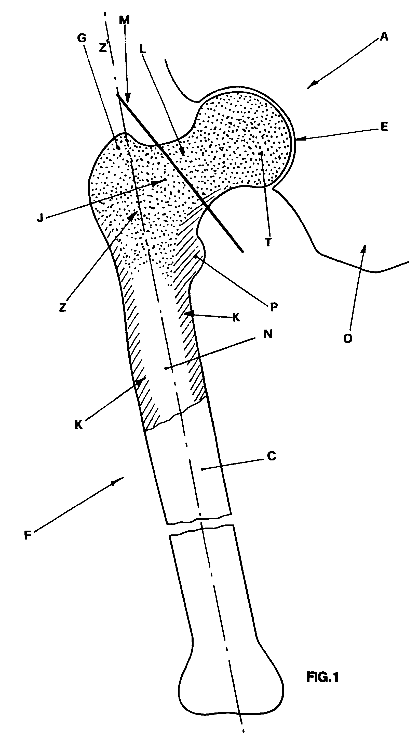
[0053]One can also see the femoral body C, with straight development, the head T of femur F articulated in the acetabular zone E and connected to the femoral body C through the neck L, the lesser and greater trochanter indicated with P and G respectively, the proximal zone Z comprised between the two trochanters and the femoral canal N in the femoral body C in which the prosthetic stem is inserted.

[0054]In this connection it is adviseable to point out the internal structure of the femur F in which there is the spongy bone J and mainly located in the diaphises portion of the femur F.

[0055]One can also see in heavy lines, the osteotomy line M along which the head T of the femur F is being cut to allow to work the femoral canal N.

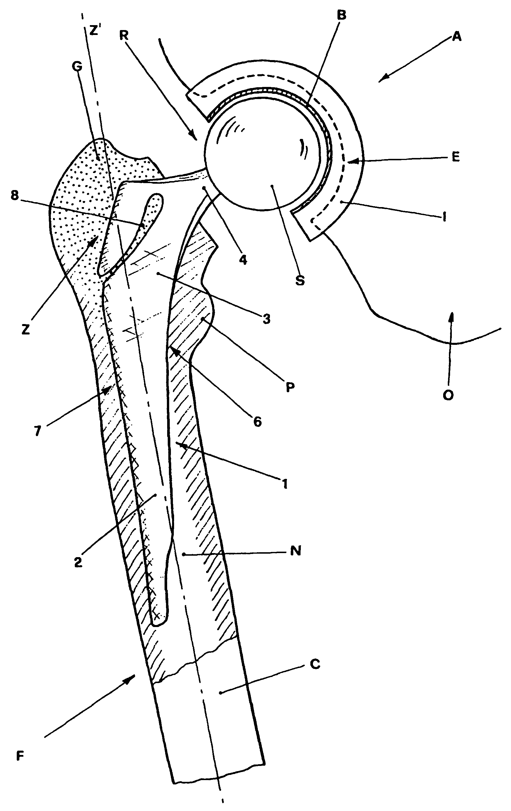
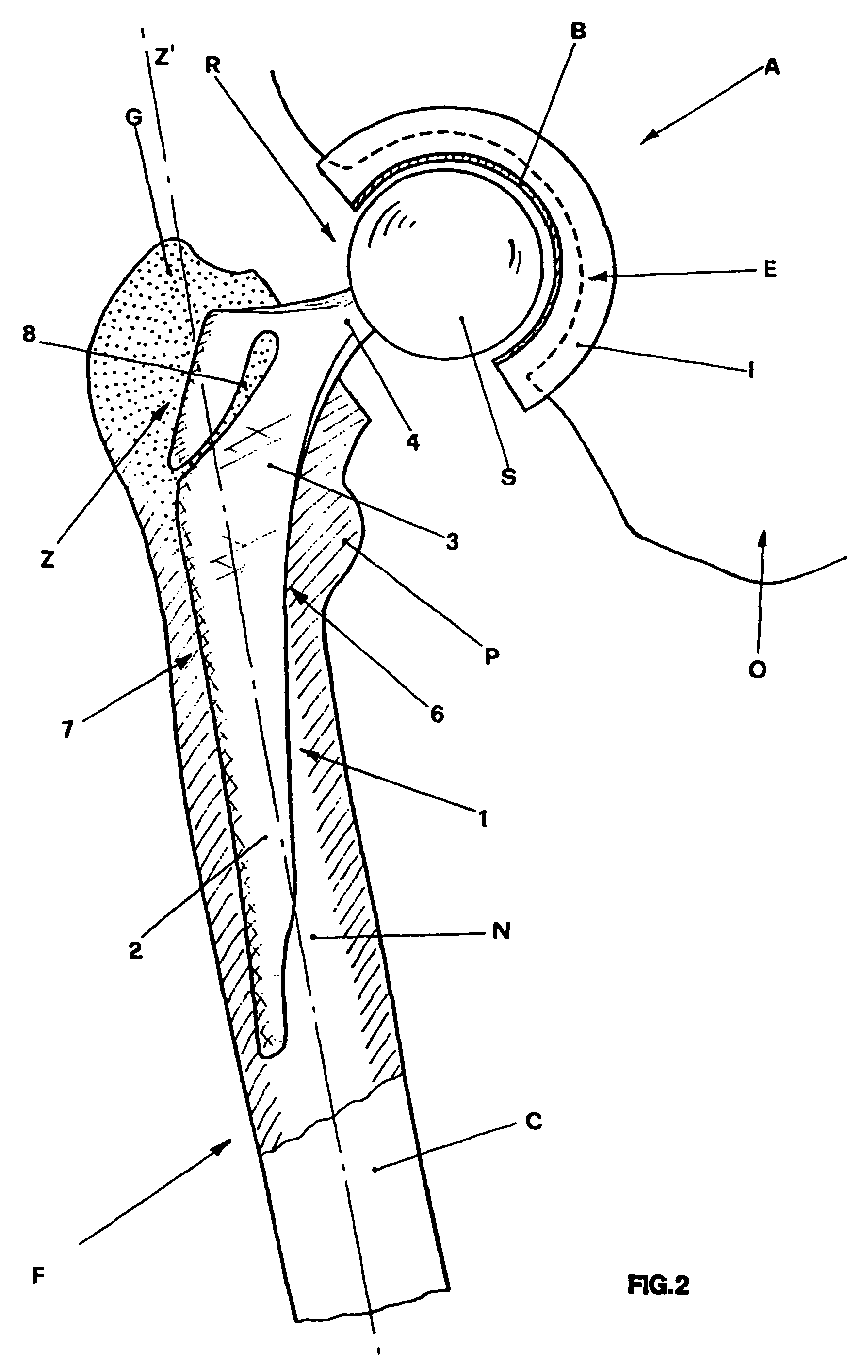
[0056]In FIG. 2 the femoral stem of the invention generally indicated with 1 and belonging to prosthesis R, is shown in the applied condition, that is inserted inside the femur F.

[0057]One can see that the femoral stem 1, preferably but not necessarily made of...


PUM

PropertyMeasurementUnit
shapeaaaaaaaaaa
thicknessaaaaaaaaaa
acute angleaaaaaaaaaa

Abstract

A femoral stem for hip prosthesis is disclosed comprising: a main body with a mainly longitudinal development and a generally wedge shaped, which is inserted into the femoral canal present in the body of the femur; a central body of a generally trapezoidal shape integral with the main body, located in the proximal zone of the femur; an appendix projecting from the central body provided with a terminal pin receiving spherical head of joint into the cotyle belonging to the prosthesis and inserted into the acetubular zone of the pelvic bone. The main body and the central body are defined by a shaped surface on one side and a mixtilinear surface on the opposite side from which a shaped notch is starting involving the central body and extending up to the proximity of the projecting appendix.

Description

BACKGROUND OF THE INVENTION[0001]The present invention relates to a femoral stem for hip prosthesis used for replacing the diseased natural joint of the hip with an artificial device taking its functions.[0002]It is well known that in the orthopaedic field surgery of the hip joint is generally carried out for old people to treat pathologies such as arthrosis, arthritis or hip luxation generating a progressive wear of the hip joint.[0003]It is well known that the hip joint connects the femur to the pelvis and comprises the femur head engaged in the acetabulum which is a joint cavity on the outer face of the pelvic bone.[0004]In the femur in addition to said femoral head there are the neck connecting the head to the femoral body, having a rather longitudinal development, and a couple of protrusions, the greater and the lesser trochanter, arranged on opposite sides on the femoral body.[0005]On the basis of the natural shape of the hip, the prosthesis to be implanted comprises therefore...

Claims


Application Information

Patent Timeline
Patent Type & Authority Patents(United States)
IPC IPC(8): A61F2/42A61F2/00A61F2/30A61F2/32A61F2/34A61F2/36
CPCA61F2/30771A61F2/367A61F2/30767A61F2/32A61F2/34A61F2/36A61F2/3676A61F2002/30116A61F2002/30212A61F2002/30326A61F2002/30879A61F2002/30892A61F2002/30934A61F2002/30955A61F2002/3611A61F2002/3625A61F2002/365A61F2002/3664A61F2002/3696A61F2230/0006A61F2230/0067A61F2250/0037A61F2310/00023A61F2310/00395A61F2310/00592A61F2002/30594A61F2002/30878
Inventor CURRADINI, GIORGIO E.
Owner CURRADINI GIORGIO E
Why Eureka
Try Eureka