
Data delivering system

Inactive Publication Date: 2008-05-20
FUJITSU LTD
View PDF22 Cites 2 Cited by
  • Summary
  • Abstract
  • Description
  • Claims
  • Application Information

AI Technical Summary

Benefits of technology

[0016]An object of the present invention is to reduce a load on a delivery source in a data delivering system. Another object of the present invention is to improve data delivery efficiency.
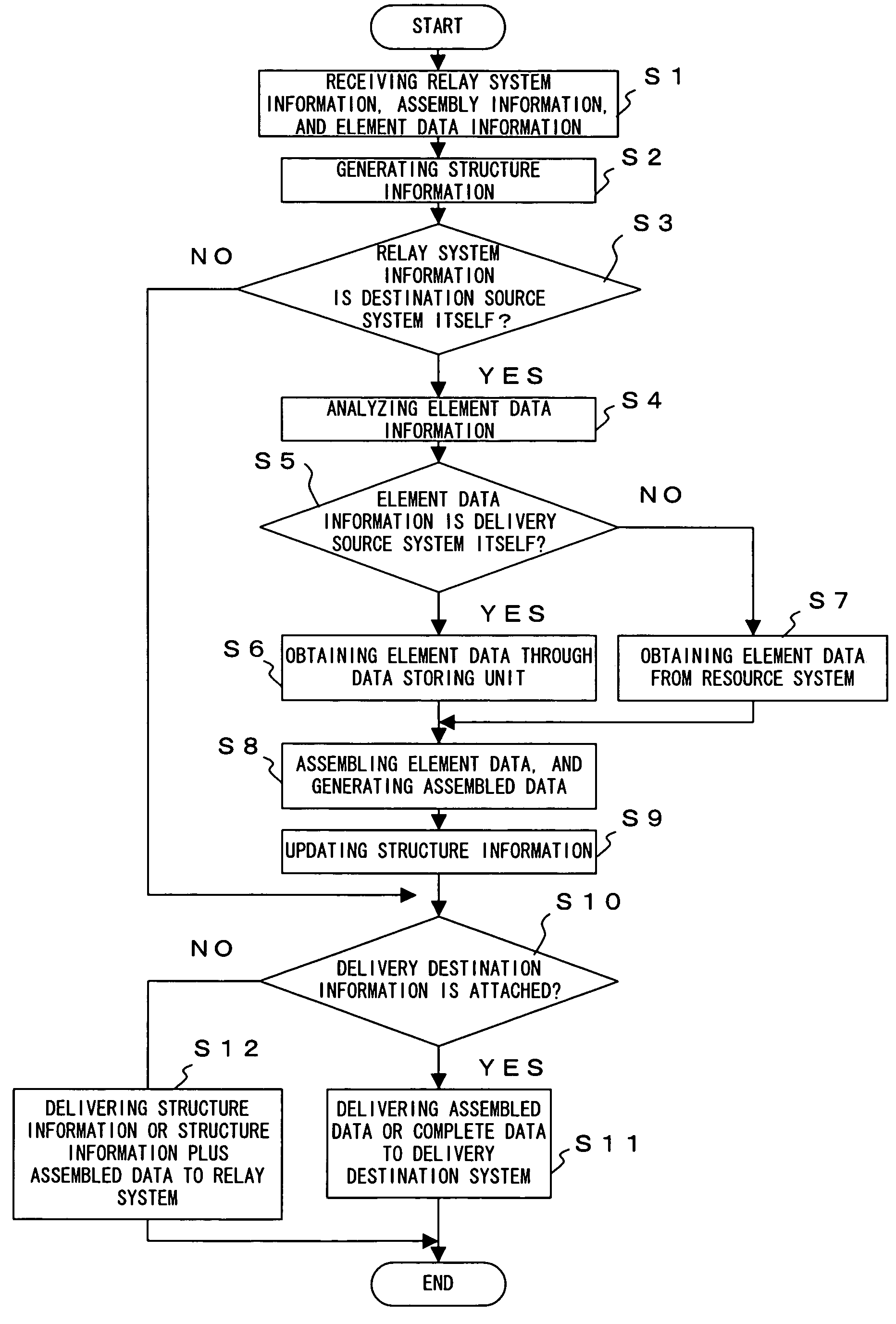
[0018]With this method, the element data to be delivered to the third device is collected by the second device. That is, the first device does not need to collect the element data to be delivered to the third device. As a result, the load on the first device as a deliver source device is reduced.
[0020]With this method, a data delivery can easily be implemented in a wide variety of forms by the descriptions of the first to the third information. For example, if a plurality of devices are specified in the second information, the plurality of specified devices can share a burden to collect the element data identified by the first information. As a result, a system with a high data delivery efficiency can be realized with ease.

Problems solved by technology

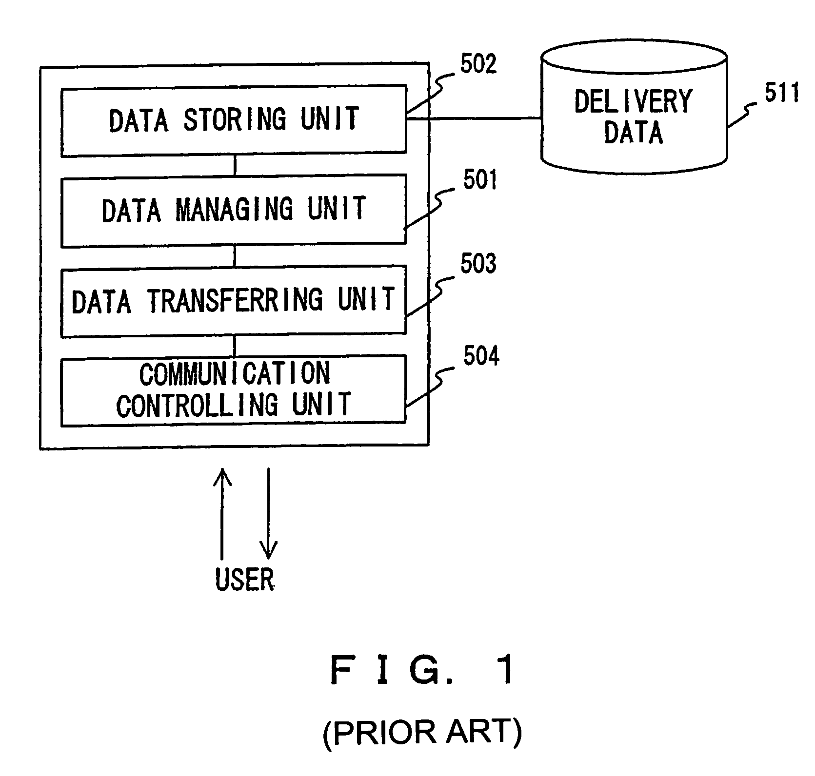
The method repeating the above described process, however, imposes a heavy load on a device at a delivery source.
On the other hand, the multi-cast transmission can only transmit the same data to all of destinations.
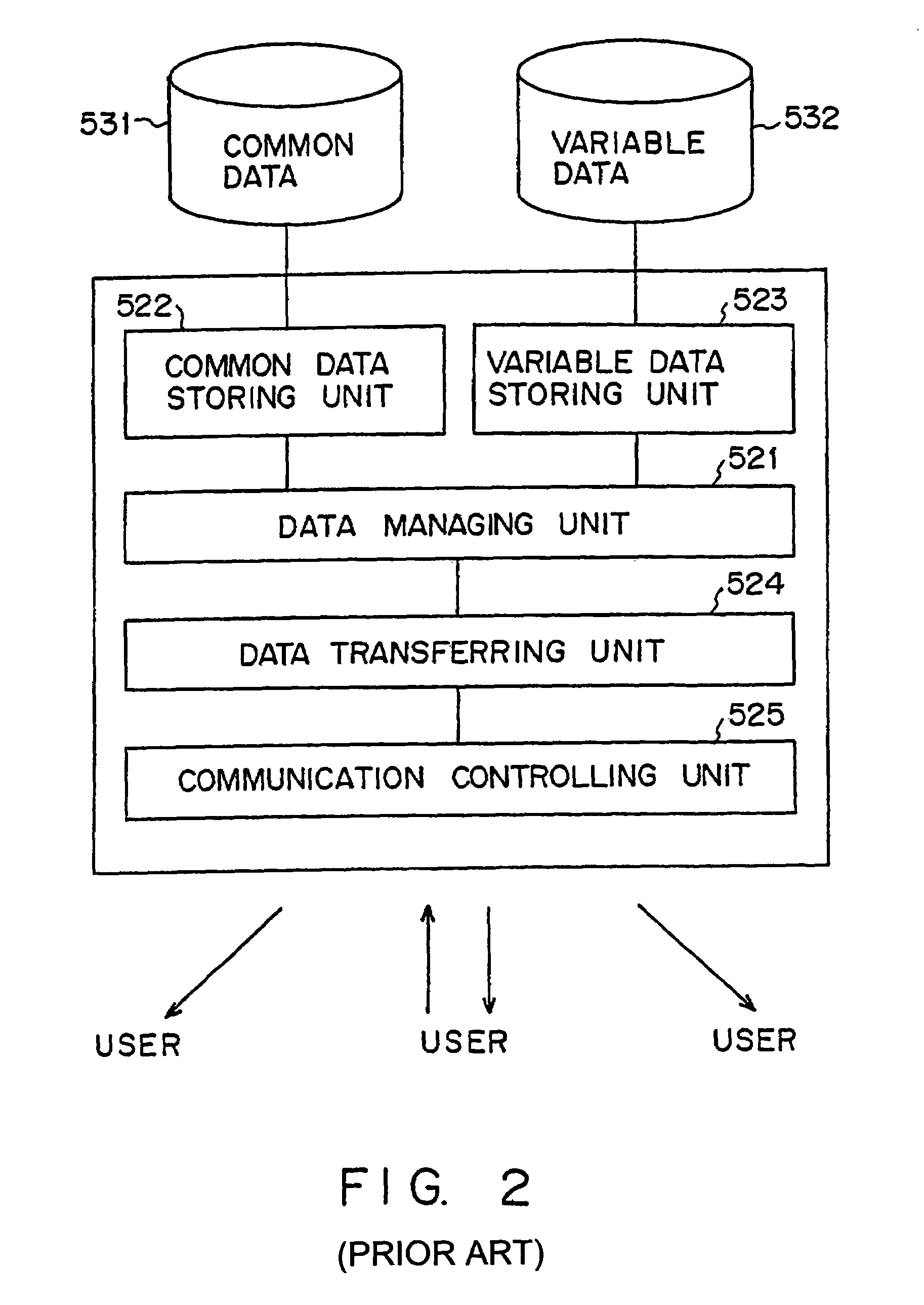
(1) A delivery source system must store all data to be delivered to corresponding destinations, or at least prepare all data to be delivered to corresponding destinations. Accordingly, the load on the delivery source system becomes heavy. Additionally, most of the known methods cannot start a data delivery until all data (to be delivered to all of destinations) are collected, when data that differs depending on each destination is delivered. Therefore a data delivery delay becomes problematic in this case.
(2) A delivery source system must store the information about all of destinations (such as IP or mail addresses, system names, or the like). Therefore, the operations for managing destinations become complicated in the delivery source system.
(3) A delivery source system must generate (or assemble) all of delivery data, when data that differs depending on each destination is delivered. Therefore, the load on the delivery source system becomes heavy.
(4) All of delivery data are output from a delivery source system, when data that differs depending on each destination is delivered. Therefore, lines or paths adjacent to the delivery source system are occupied by that data delivery.

Method used


Image

  • Data delivering system
  • Data delivering system
  • Data delivering system

Examples


first embodiment

[0152]The first embodiment relates to a newspaper delivering system which delivers newspaper articles to subscribers as electronic data. The data delivering method shown in FIGS. 13 through 15 is used in this system.

[0153]With this newspaper delivering system, each subscriber can receive nationwide and local news. To implement such a data delivery, a headquarters system 101 provides all of subscribers with the nationwide news to be delivered, and branch systems 103a through 103c (a branch-A system 103a through a branch-C system 103c) respectively provide the subscribers with local news. Here, the headquarters system 101 functions as a delivery source system, whereas the branch systems 103a through 103c function as relay systems respectively.

[0154]FIG. 22 exemplifies the structure information used in the first embodiment. This structure information includes the structure information portion for the headquarter system 101, and the structure information portions for the respective bran...

second embodiment

[0165]The second embodiment relates to an operational data delivering system which delivers the information about operations from a general affairs division in a company to respective employees. This system utilizes the data delivering method shown in FIGS. 15 and 16.

[0166]The operational data delivering system according to this embodiment assumes that templates (such as a spreadsheet format) of a job achievement (business performance) report, an in-office memo, a business trip expense adjustment statement are distributed to employees beforehand. These templates may be distributed by using a storage medium such as a CD-ROM, a floppy disk, etc., or via a network. In either case, these templates are assumed to be prestored onto a storage medium 114 (hard disk, etc.) comprised by a terminal 113 for each employee. A general affairs division system 111 periodically delivers the raw data of the job achievement report, the in-office memo, and the business trip expense adjustment statement ...

third embodiment

[0170]The third embodiment relates to a newspaper delivering system which delivers newspaper articles to subscribers as electronic data. In this system, the structure data is described in an XML (eXtensible Markup Language).

[0171]With this newspaper delivering system, world news is delivered from headquarters to branches, and is further delivered to subscribers after local news (Asian news, Japanese news, or the like) is attached by each of the branches depending on need.

[0172]Specifically, a headquarters system 201 is arranged in New York, and comprises a database 202 for storing “world news”. Additionally, the headquarters system 201 comprises a subscriber list 203 for storing subscriber information (including addresses). This subscriber list 203 stores the information of United States and Yugoslavian subscribers. The headquarters system 201 delivers “world news” to U.S. subscribers U-1 through U-n, and also delivers the news to a Yugoslavian branch system 211 and an Asian branch ...


PUM


Abstract

A headquarters system generates structure information, and obtains nationwide news from a resource system according to the structure information. The headquarters system delivers the structure information and the nationwide news to a branch system. The branch system obtains local news from a resource system according to the structure information received from the headquarters system, and delivers the nationwide news and the local news to a plurality of destinations according to the structure information.

Description

BACKGROUND OF THE INVENTION[0001]1. Field of the Invention[0002]The present invention relates to a method for delivering data to devices connected via a communications network.[0003]2. Description of the Related Art[0004]Generally, when data is delivered, a device at a delivery source must prepare the information identifying a delivery destination (hereinafter referred to as “destination information” or “delivery destination information”), and data to be delivered for each delivery destination.[0005]FIG. 1 explains an existing general data delivering system. This figure depicts the device at a data delivery source and an external storage medium accessed by this device. Note that this system is assumed to deliver data based on a user instruction (delivery request).[0006]A data managing unit 501 makes a data storing unit 502 collect the data corresponding to a user instruction. The data storing unit 502 obtains the data to be delivered to a user from an external storage medium 511 acc...

Claims


Application Information

Patent Timeline
IPC IPC(8): G06F15/173G06F15/16G06F13/00H04L12/46H04L12/54
CPCH04H20/06H04H20/103H04L67/2842H04L67/28H04L67/2885H04L67/56H04L67/568
Inventor ODA, YASUTAKAHAYASHI, KATZUMIKIMURA, MASAYAUJIGAWA, TAICHI
Owner FUJITSU LTD
Learn More