Bypass duct fluid cooler
a technology of duct fluid cooler and bypass duct, which is applied in the direction of machines/engines, vessel construction, marine propulsion, etc., can solve problems such as engine operation problems, and achieve the effect of light weigh
- Summary
- Abstract
- Description
- Claims
- Application Information
AI Technical Summary
Benefits of technology
Problems solved by technology
Method used
Image
Examples
Embodiment Construction
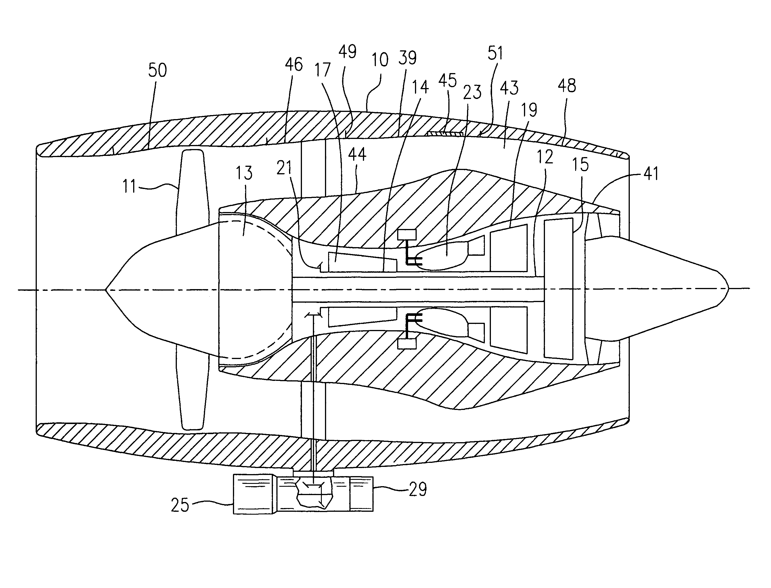
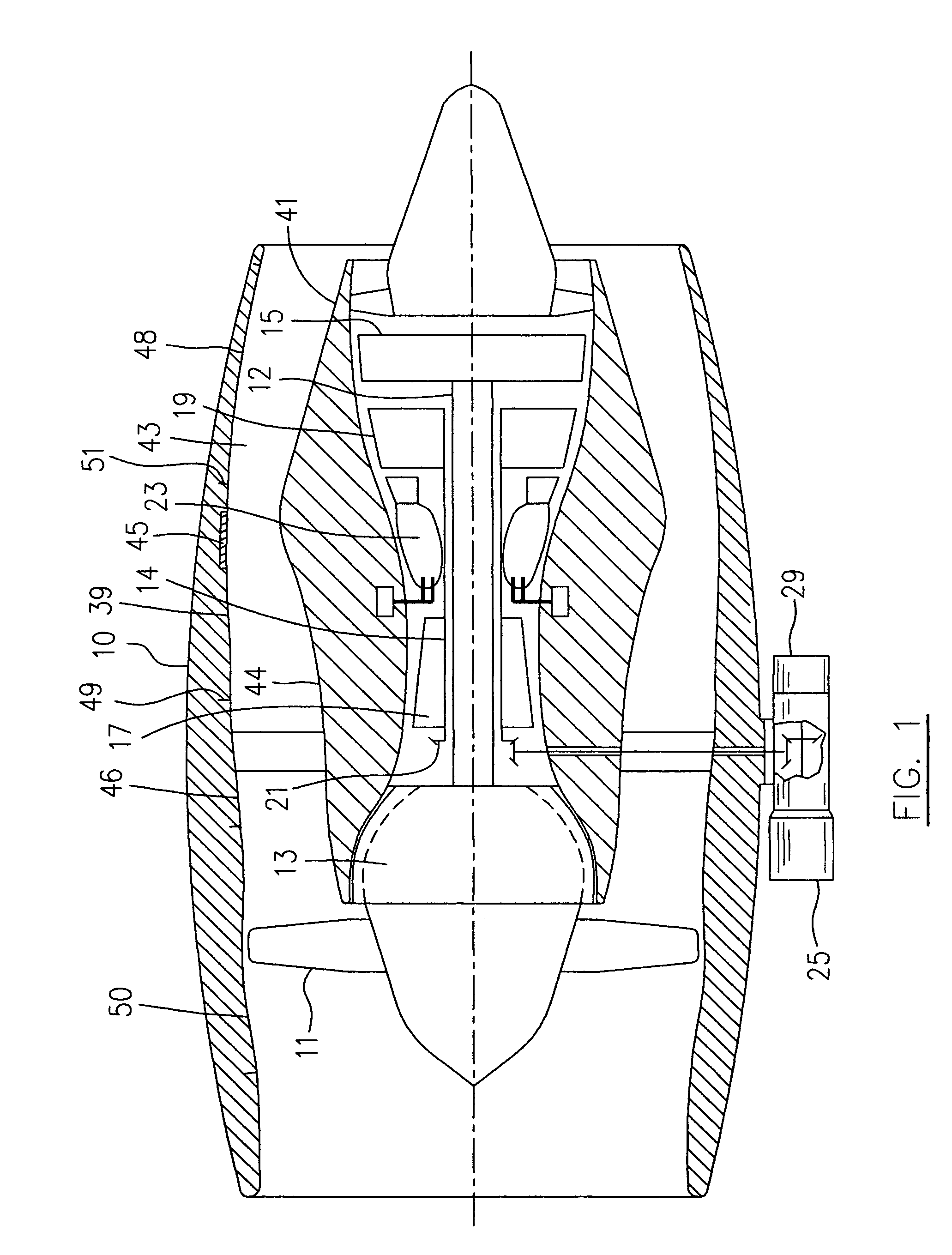
[0016]A bypass gas turbine engine seen generally in FIG. 1 includes a housing nacelle 10, a low-pressure spool assembly seen generally at 12 which includes a fan 11, a low-pressure compressor 13 and a low-pressure turbine 15, a high-pressure spool assembly seen generally at 14 which includes a high-pressure compressor 17, a high-pressure turbine 19 and a gear 21, a combustor 23 and an accessory-drive assembly 25. An annular bypass duct 43 is defined between an inner bypass duct wall 44 and an outer bypass duct wall 39. A stream of bypass air which is compressed by the fan 11, is directed through the annular bypass duct 43 and discharged therefrom to produce thrust.
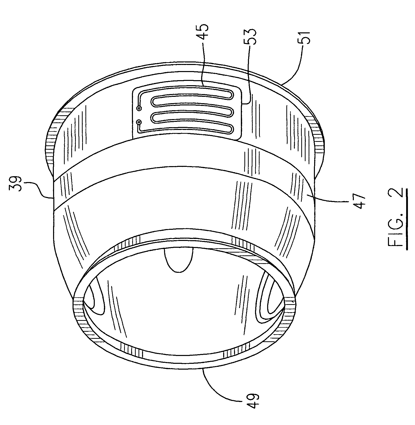
[0017]The engine has a lubricating system (not indicated) including a pump 29 and a heat-exchanger 45 mounted in this embodiment, to the outer bypass duct wall 39. The heat exchanger 45 is connected in fluid communication with the lubricating system of the engine to allow relatively hot oil to flow therethrough and be ther...
PUM
 Abstract
Description
Claims
Application Information
 - R&D
- Intellectual Property
- Life Sciences
- Materials
- Tech Scout
- Unparalleled Data Quality
- Higher Quality Content
- 60% Fewer Hallucinations
Browse by: Latest US Patents, China's latest patents, Technical Efficacy Thesaurus, Application Domain, Technology Topic, Popular Technical Reports.
© 2025 PatSnap. All rights reserved.Legal|Privacy policy|Modern Slavery Act Transparency Statement|Sitemap|About US| Contact US: help@patsnap.com


