

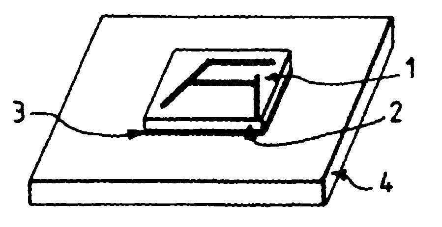
Process for securing a microwave module to a support
a technology for microwave modules and supports, applied in the field of microwaves, can solve the problems of loss of signal energy by reflection, interference with other elements of the circuit, and part of the signal may propagate, so as to reduce the quantity of adhesive deposited and the cost of the process
- Summary
- Abstract
- Description
- Claims
- Application Information
AI Technical Summary
Benefits of technology
Problems solved by technology
Method used
Image

Examples
Embodiment Construction
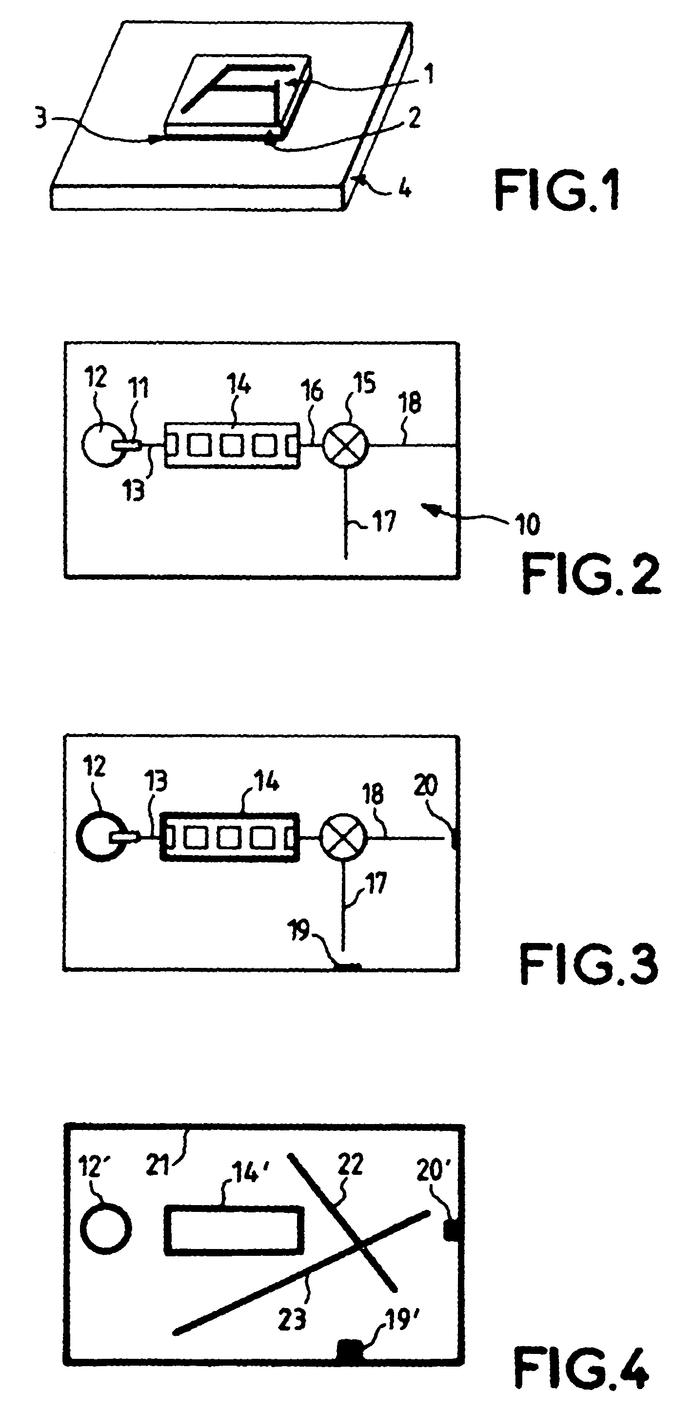
[0015]To simplify the description, in the figures the same elements bear the same references.
[0016]The application of the present invention to the case of a 40 GHz millimetre receiver will be described with reference to FIGS. 2, 3 and 4. As represented in FIG. 2, on a substrate 10 which may be made in a known manner from “Teflon” glass, has firstly been made a transition 11 between a circular guide 12 and a microstrip line 13 for the reception of the millimetre signal, namely the 40 GHz signal. The circuit also comprises a bandpass filter 14 receiving as input the millimetre signal transported by the microstrip line 13. The bandpass filter 14 is made in suspended microstrip line technology, its purpose being to filter the useful signal and to reject the image frequency and the leaks of the local oscillator. Mounted at the output of the bandpass filter 14 is a mixer 15 connected to the filter by a microstrip line 16. Moreover, a local oscillator (not represented) is connected to the ...
PUM
| Property | Measurement | Unit |
|---|---|---|
| conducting | aaaaa | aaaaa |
| conductive | aaaaa | aaaaa |
| perimeter | aaaaa | aaaaa |
Abstract
Description
Claims
Application Information