Planar microwave line having microstrip conductors with a directional change region including a gap having periodic foldings

a microstrip conductor and directional change technology, applied in the field of planar microwave lines, can solve the problems of undesirable signal corruption, shift in electrical ground zero point, electrical field, etc., and achieve the effect of reducing wave impedance and reducing wave impedan

Active Publication Date: 2008-05-27
ATMEL CORP
View PDF6 Cites 5 Cited by
  • Summary
  • Abstract
  • Description
  • Claims
  • Application Information

AI Technical Summary

Benefits of technology

[0016]This embodiment provides a coplanar line that can be used as a more cost-effective replacement for a coaxial line. A particular advantage of the invention is that it can also be used in such coplanar lines. During application of the subject of DE 29 43 502 to a coplanar line, on the contrary, a transposition of signal conductors and screening conductors would occur, which would interfere with the screening functionality of the coplanar line. It is also preferred that the gap between the first microstrip conductor and each additional microstrip conductor in the first region and in the second region is constant in each case and in the transition region has a periodic modulation around an average value, which corresponds to the gap in the first region and / or in the second region.
[0017]In addition to length uniformity, extensive constancy of the microwave line wave impedance, which depends on the gap of the microstrip conductor, is further achieved by the invention. Sections with a larger gap and thereby greater wave impedance and sections with a smaller gap and thereby lower wave impedance counterbalance in the ideal case.
[0018]Furthermore, a periodic modulation of the gap occurs as the result of a periodic folding of at least one inner edge, which has a certain wavelength.
[0019]An inner edge can be lengthened as desired by such periodic folding and thereby matched to the length of another outer edge of an adjacent microstrip conductor with a higher curvature radius.
[0020]It is also preferable that the periodic modulation of the gap arises due to folding of opposite edges of adjacent microstrip lines having different wavelengths.
[0021]By this embodiment, convexities in the paths of the edges can largely approach the ideal of a parallel path, so that deviations in the gap between both edges from an average value are very low.

Problems solved by technology

It is also known that discontinuities in the signal path such as open ends, feed-throughs through the dielectric, wave resistance jumps, crossing of lines, or directional changes, for example, breaks in the path of lines, produce distortions in the electromagnetic fields, which corrupts transmitted signals.
With directional changes, as occur, for example, in a routing in arcs, on the contrary, undesirable signal corruptions and shifts in the electrical ground-zero point occur.
The prior-art microwave line with the interruptions and the conducting jumper extending from the plane into the third dimension also exhibits discontinuities and thereby undesirable wave resistance increases.

Method used


Image

  • Planar microwave line having microstrip conductors with a directional change region including a gap having periodic foldings
  • Planar microwave line having microstrip conductors with a directional change region including a gap having periodic foldings
  • Planar microwave line having microstrip conductors with a directional change region including a gap having periodic foldings

Examples


Embodiment Construction

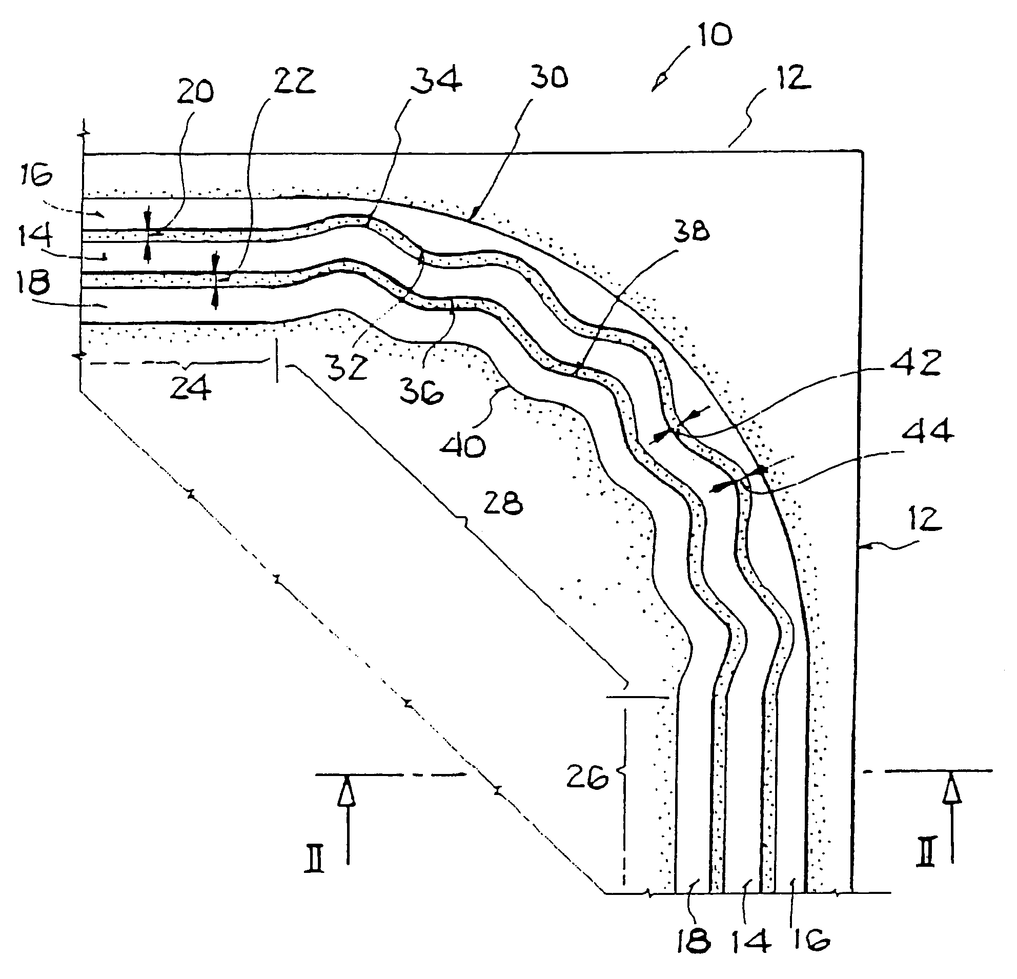
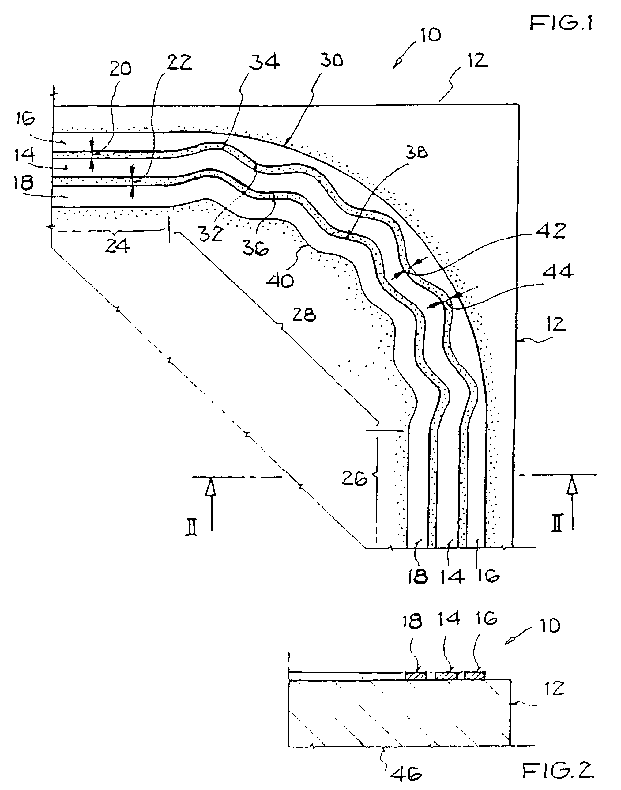
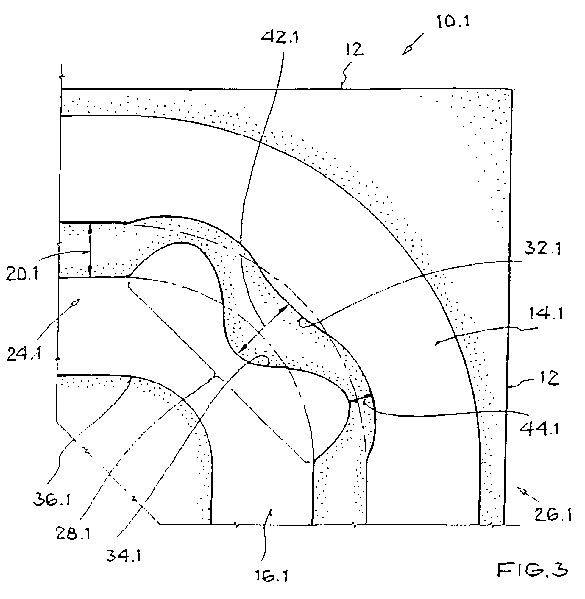
[0035]FIG. 1 shows a planar microwave line 10 in detail, which extends to a dielectric substrate 12 and has a first microstrip conductor 14 and two additional microstrip conductors 16 and 18. FIG. 1 thereby shows a coplanar line as microwave line 10. The coplanar line corresponds to a planar coaxial line. A first gap 20 between the first microstrip conductor 14 and a second microstrip conductor 16 as an additional microstrip conductor is dimensioned in such a way that during the transmission of microwaves an electromagnetic coupling occurs between the first microstrip conductor 14 and the second microstrip conductor 16. Analogously, a second gap 22 between the first microstrip conductor 14 and a third microstrip conductor 18 as an additional microstrip conductor is dimensioned in such a way that during the transmission of microwaves, an electromagnetic coupling occurs between the first microstrip conductor 14 and the third microstrip conductor 18.

[0036]The first microstrip conductor...


PUM


Abstract

A planar microwave line is provided, having a dielectric substrate and a planar arrangement of a first microstrip conductor and at least one additional microstrip conductor, in which a gap between the first microstrip conductor and the additional microstrip conductor permits an electromagnetic coupling, a first region in which the microwave line has a first direction, a second region in which the microwave line has a second direction, and a transition region in which a change from the first direction to the second direction occurs. The microwave line is characterized in that the adjacent edges of the first microstrip conductor and of the additional microstrip conductor in the transition region are equal in length and do not cross.

Description

[0001]This nonprovisional application claims priority under 35 U.S.C. § 119(a) on German Patent Application Nos. DE 10200538456.0 and DE 102004053517.5, which were filed in Germany on Aug. 3, 2005 and Oct. 29, 2004, respectively, and which are herein incorporated by reference.BACKGROUND OF THE INVENTION[0002]1. Field of the Invention[0003]The present invention relates to a planar microwave line having a dielectric substrate and a planar arrangement of a first microstrip conductor and at least one additional microstrip conductor, in which a gap between the first microstrip conductor and the additional microstrip conductor permits an electromagnetic coupling, to a first region in which the microwave line has a first direction, to a second region, in which the microwave line has a second direction, and to a transition region in which a change from the first direction to the second direction occurs. The invention relates further to a method for guiding a microwave, which propagates in t...

Claims


Application Information

Patent Timeline
Patent Type & Authority Patents(United States)
IPC IPC(8): H01P3/08
CPCH01P1/02H01P3/003H01P5/185
Inventor ZIMMERLING, DETLEF
Owner ATMEL CORP
Why Eureka
Try Eureka