
Quantum vacuum energy extraction

a technology of quantum vacuum and energy extraction, applied in the direction of starting point details, position/direction control, spraying power supply, etc., can solve the problems of inability to remove this last amount of random energy from an oscillating system, rendering stable matter impossible, and inability to achieve the effect of removing the last random energy amoun

Active Publication Date: 2008-05-27
UNIV OF COLORADO THE REGENTS OF
View PDF5 Cites 33 Cited by
  • Summary
  • Abstract
  • Description
  • Claims
  • Application Information

AI Technical Summary

Problems solved by technology

However this was not feasible.
The orbiting electron(s) would emit Larmor radiation, quickly losing energy and thus spiraling into the nucleus on time scales less than one-trillionth of a second, thereby rendering stable matter impossible.
It is thus impossible to remove this last amount of random energy from an oscillating system.
A clear consequence of this theory is that a reduction of the electromagnetic quantum vacuum at the frequency corresponding to the orbit of the electron will result in a decay of the orbit since there will thereby be an imbalance in the Larmor radiation vs. absorption.
Indeed, a thought experiment by Forward (1984) showed a simple, but not practical, energy extraction experiment.
Yes, the ocean is being depleted thereby, but no practical consequences ensue.

Method used


Image

  • Quantum vacuum energy extraction
  • Quantum vacuum energy extraction
  • Quantum vacuum energy extraction

Examples


Embodiment Construction

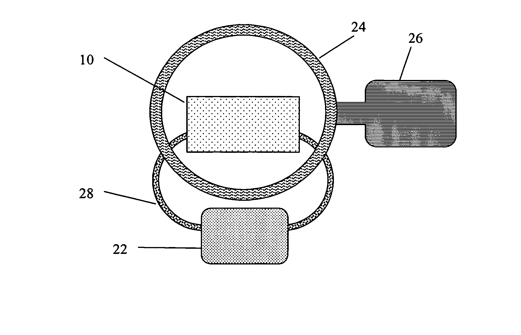
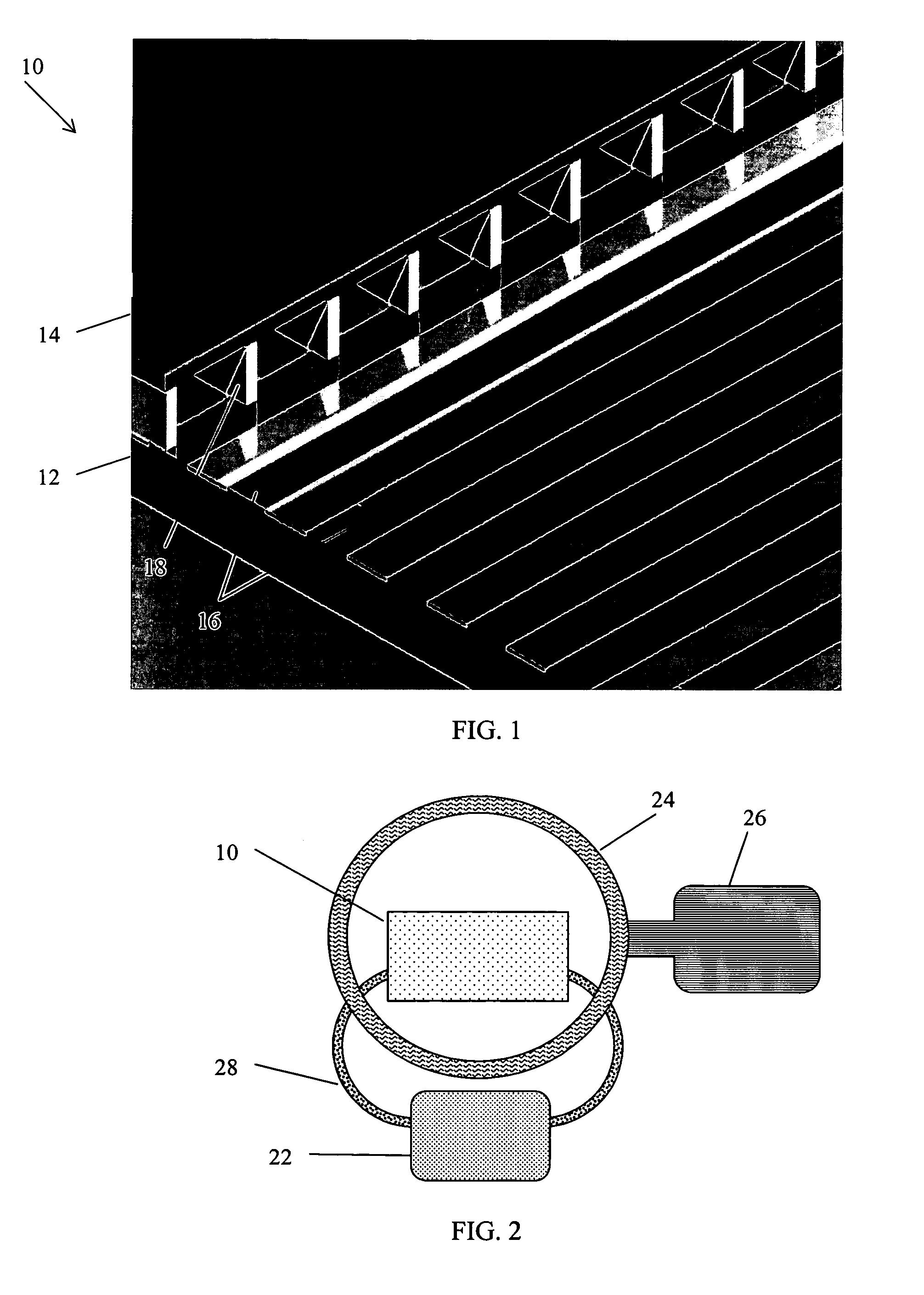
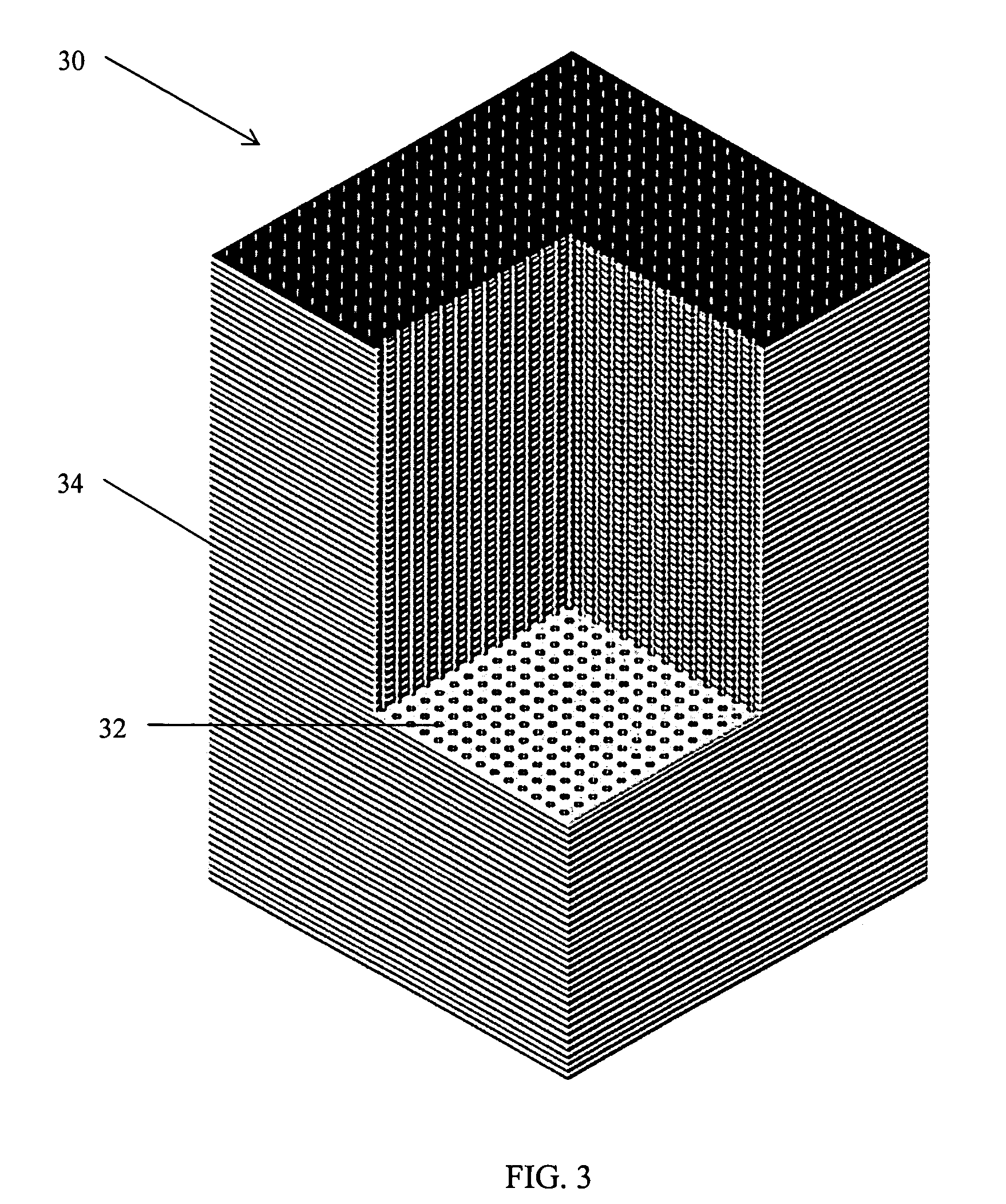
[0052]The first embodiments of this concept utilize Casimir cavities consisting of volumes through which, or in and out of which, gases flow, and which on the size scales of atoms appear as regions bounded by parallel plates of conducting material in which the plate scales are much larger than the plate separations; or by cylinders of conducting material in which the lengths of the cylinders are much larger than the diameters. It is claimed that other forms of Casimir cavity are capable of producing a similar effect, and the term Casimir cavity will be used to designate any volume capable of mode suppression of the zero-point field. The necessary condition is that the mode suppression ability of the Casimir cavity be matched to the electron energy levels in such a way as to result in a significant difference of the electron energy levels inside vs. outside the cavity.

[0053]These embodiments demonstrate the following concepts:[0054]A method, comprising: (a) use of a device including ...


PUM


Abstract

A system is disclosed for converting energy from the electromagnetic quantum vacuum available at any point in the universe to usable energy in the form of heat, electricity, mechanical energy or other forms of power. By suppressing electromagnetic quantum vacuum energy at appropriate frequencies a change may be effected in the electron energy levels which will result in the emission or release of energy. Mode suppression of electromagnetic quantum vacuum radiation is known to take place in Casimir cavities. A Casimir cavity refers to any region in which electromagnetic modes are suppressed or restricted. When atoms enter into suitable micro Casimir cavities a decrease in the orbital energies of electrons in atoms will thus occur. Such energy will be captured in the claimed devices. Upon emergence form such micro Casimir cavities the atoms will be re-energized by the ambient electromagnetic quantum vacuum. In this way energy is extracted locally and replenished globally from and by the electromagnetic quantum vacuum. This process may be repeated an unlimited number of times. This process is also consistent with the conservation of energy in that all usable energy does come at the expense of the energy content of the electromagnetic quantum vacuum. Similar effects may be produced by acting upon molecular bonds. Devices are described in which gas is recycled through a multiplicity of Casimir cavities. The disclosed devices are scalable in size and energy output for applications ranging from replacements for small batteries to power plant sized generators of electricity.

Description

BACKGROUND OF THE INVENTION[0001]Max Planck proposed the concept of zero-point energy in 1912. The idea was then studied by Albert Einstein and Otto Stern in 1913. In 1916 Walther Nernst proposed that the Universe was filled with zero-point energy. The modern field of stochastic electrodynamics is based upon these ideas.[0002]At that same time the structure and stability of the atom were puzzles. The Rutherford model of the atom was based on analogy to the motions of planets (electrons) around the Sun (the nucleus). However this was not feasible. The orbiting electron(s) would emit Larmor radiation, quickly losing energy and thus spiraling into the nucleus on time scales less than one-trillionth of a second, thereby rendering stable matter impossible. It is now known within the context of stochastic electrodynamics (SED) theory that a possible solution involves the absorption of zero-point energy. It was shown in 1975 by Boyer that the simplest possible atom and atomic state, the hy...

Claims


Application Information

Patent Timeline
Patent Type & Authority Patents(United States)
IPC IPC(8): H02N11/00H02M1/00
CPCH02N11/002
Inventor HAISCH, BERNARDMODDEL, GARRET
Owner UNIV OF COLORADO THE REGENTS OF
Learn More