Machining technique with selective and localized placement of tooling material

a tooling material and tooling technology, applied in the field of milling and machining processes, can solve the problems of only being able to use picture framing, affecting requiring significant scrap, so as to improve the performance of the frame, reduce the weight, and be convenient to use.

Active Publication Date: 2008-06-03
THE BOEING CO
View PDF21 Cites 0 Cited by
  • Summary
  • Abstract
  • Description
  • Claims
  • Application Information

AI Technical Summary

Benefits of technology

[0008]The embodiments of the present invention provide several advantages. One such advantage is the provision of holding a workpiece on a machining table without the need for a significant amount of excess material commonly associated with picture framing.
[0009]The present invention provides a simple, inexpensive, and efficient technique for grabbing and rigidly fixing a workpiece, having dimensions approximately the same as or greater than that of a resultant component to be formed, on a worktable.
[0010]The present invention efficiently utilizes available stock materials that may otherwise be scrapped or recycled due to inadequate size thereof.
[0011]The present invention also provides an increase in performance of components that may normally be formed of multiple pieces, due to the lack of adequately sized stock for unitary component formation. As such, the present invention reduces weight and minimizes crack initiation sites and potential leak paths.

Problems solved by technology
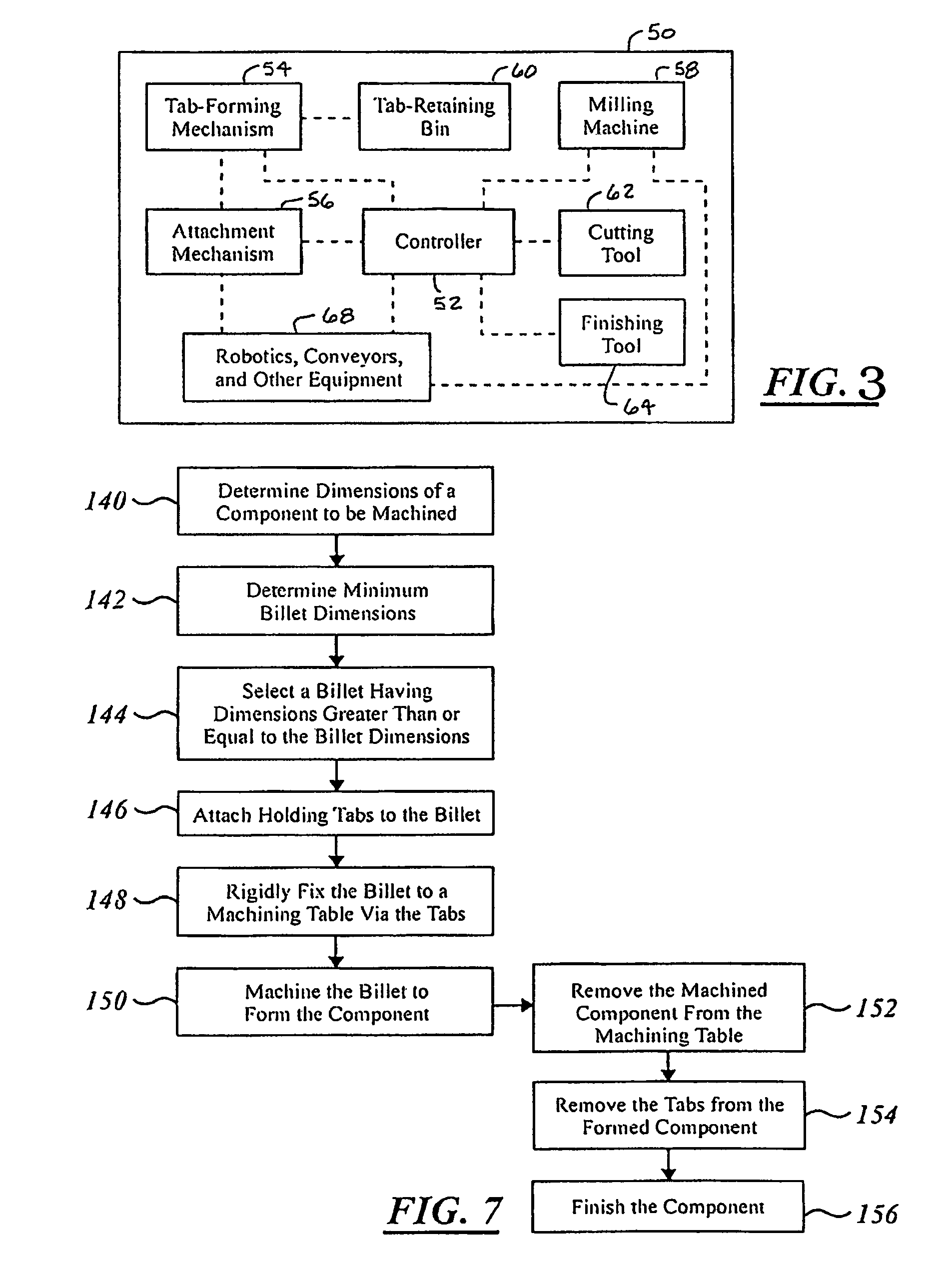
Although picture framing provides a simple technique for milling a component, it has associated disadvantages.
One such disadvantage is the inclusion of the excess material to form the frame.
For large parts this excess material is costly and can result in a significant amount of scrap.
In addition, picture framing can only be used when a piece of stock is available that is of proper size to accommodate for the dimensions of the component being machined, as well as for the required and associated framing dimensions.
There are often incidents when the stock available is large enough to accommodate only the dimensions of the component and not of a frame.
As a result, that component must be machined and assembled as multiple elements or cannot be machined until a billet of material of adequate size is ordered, shipped, and received.
The machining and assembling of multiple elements, as opposed to a single unitary structure, can add undesired weight, costs, manufacturing time, and complexity to a system.
The assembling or joining of elements reduces the strength of the resultant component, which can lead to fatigue cracks and corrosion.

Method used


Image

  • Machining technique with selective and localized placement of tooling material
  • Machining technique with selective and localized placement of tooling material
  • Machining technique with selective and localized placement of tooling material

Examples


Embodiment Construction

[0022]In each of the following Figures, the same reference numerals are used to refer to the same components. The present invention provides various machining techniques that may be utilized in forming or creating various components for aeronautical applications, land-based vehicle applications, non-vehicle applications, or other applications known in the art that require similar machining.

[0023]In the following description, various operating parameters and components are described for one constructed embodiment. These specific parameters and components are included as examples and are not meant to be limiting.

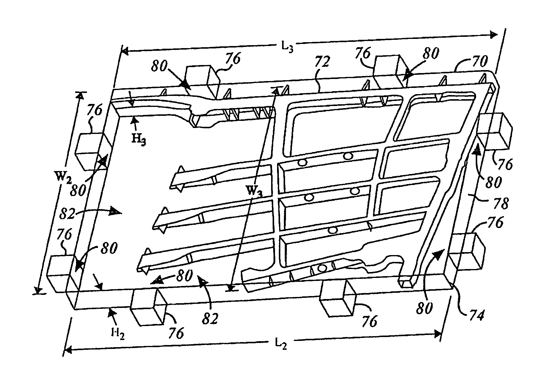
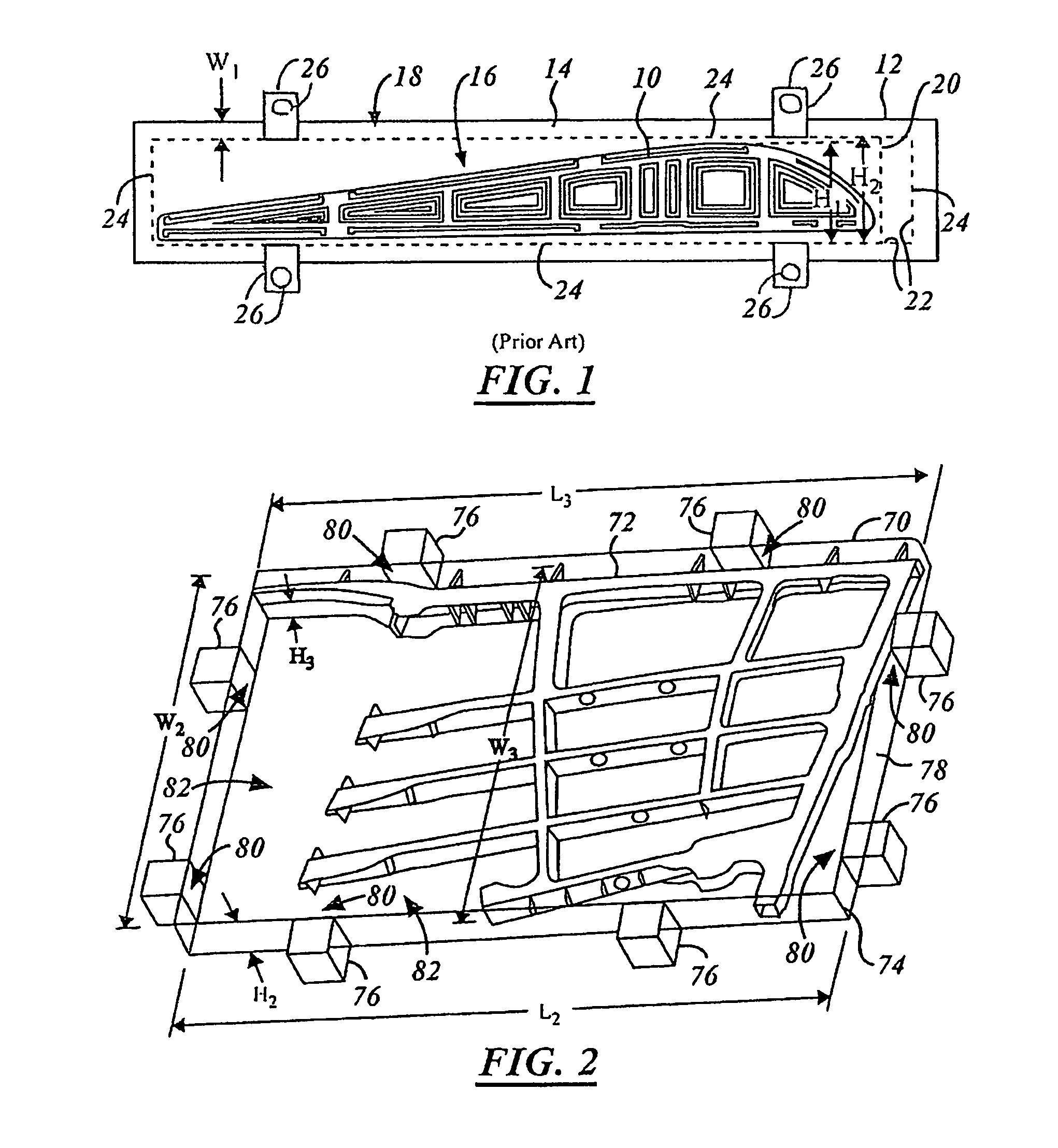
[0024]Also, in the following description the terms “billet” or “billet of material” refers to a stock piece of material, which may be in a solid or hollow semi-finished form. A billet may be used to form long tubular products such as bars and channels. A billet may be generally round or square in shape or may be of various other shapes. A billet has been hot worked by forging,...


PUM

PropertyMeasurementUnit
sizeaaaaaaaaaa
width W1aaaaaaaaaa
outer dimensionsaaaaaaaaaa

Abstract

A method of holding a billet of material (70) to a machining table (106) includes determining a first set of outer dimensions of a component (72) to be machined. The billet of material (70) is selected in response to the first set of outer dimensions to have a second set of outer dimensions. Dimensions of the second set of outer dimensions are approximately equal to or greater than corresponding dimensions of the first set of outer dimensions. Multiple tabs (76) are attached to the billet of material (70). The tabs (76) are rigidly fixed to the machining table (106). A machining system (50) includes a controller (52) that determines a first set of outer dimensions of a component (72) to be machined. A tab-forming mechanism (54) generates multiple tabs (76) that are configured to be rigidly fixed to a machining table (106). An attachment mechanism (56) couples the tabs (76) to a billet of material (70), which has a second set of outer dimensions having the same relation to the first set of outer dimensions previously stated.

Description

TECHNICAL FIELD[0001]The present invention relates generally to milling and machining processes, more particularly, to the techniques used in preparation of and during the stated processes.BACKGROUND OF THE INVENTION[0002]One technique commonly used in industry as part of a milling or machining process to hold a component, such as an airfoil for an aircraft, is referred to as “picture framing”. In machining the component, a center portion of a large billet or block of raw material, consisting typically of steel or aluminum, is machined to form the component. The block of material is oversized such that a predetermined amount of excess material exists around the outer perimeter of the center portion. This excess material forms a “frame” upon which clamps can be fastened to hold the block in place on a milling table during the machining process.[0003]Although picture framing provides a simple technique for milling a component, it has associated disadvantages. One such disadvantage is ...

Claims


Application Information

Patent Timeline
Patent Type & Authority Patents(United States)
IPC IPC(8): B23P15/02B21K3/00
CPCB23Q3/06Y10T29/49826Y10T29/49996Y10T29/5191Y10T409/30868
Inventor STERN, ERIC J.HELVEY, AMY M.HECK, DAVID P.MARTIN, RICKY L.
Owner THE BOEING CO
Why Eureka
Try Eureka