
Cutting tool

a cutting tool and cutting tool technology, applied in the field of cutting tools, can solve the problems of obstructing the downsizing of the main body, deteriorating usability, affecting the operation of the tool, etc., and achieves the effects of effective operation, excellent operability, and effective preventing the blockage of the chip

Active Publication Date: 2008-06-03
MAKITA CORP
View PDF21 Cites 22 Cited by
  • Summary
  • Abstract
  • Description
  • Claims
  • Application Information

AI Technical Summary

Benefits of technology

The solution enables effective dust collection without dispersion, prevents clogging, and allows for a compact main body design while maintaining usability and efficient airflow, even with a depth guide housed within the blade case.

Problems solved by technology

In this kind of circular saw, during cutting operation chips generated from the workpiece flow out to cause a problem of recognizing a black cut line, which deteriorates the working environment.
Because of this, a large blade case is required, which obstructs downsizing of the main body and deteriorates usability.
Since the depth guide is housed in the blade case, the airflow generated by rotation of the saw blade could be disturbed by the depth guide, which lowers the dust collecting operation.
Further, another problem occurs, that is, chips might be scattered during cutting depth adjustment as they are adhered to the depth guide.

Method used


Image

  • Cutting tool
  • Cutting tool
  • Cutting tool

Examples


Embodiment Construction

[0025]Hereinafter, an embodiment according to the present invention is described based on the drawings.

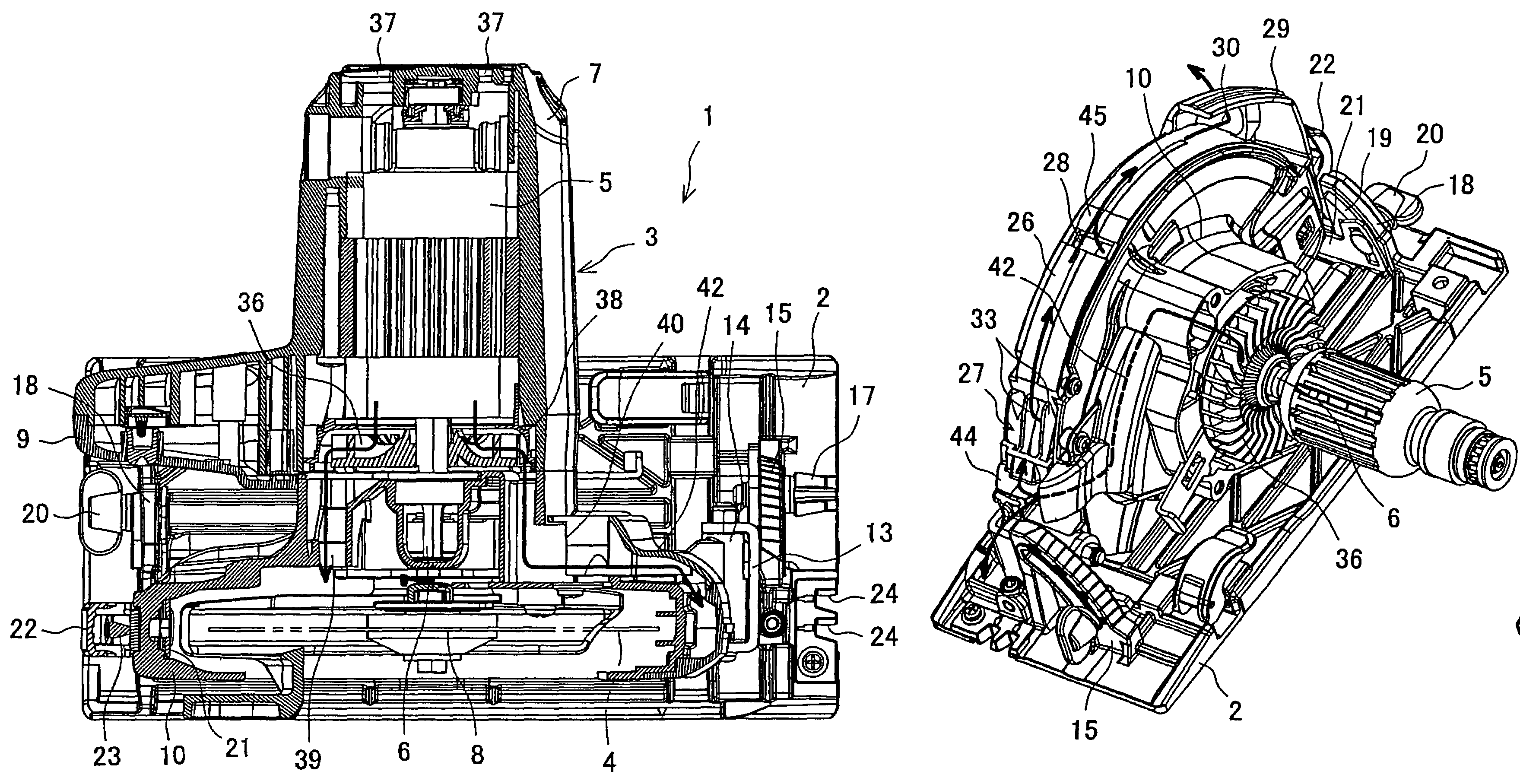
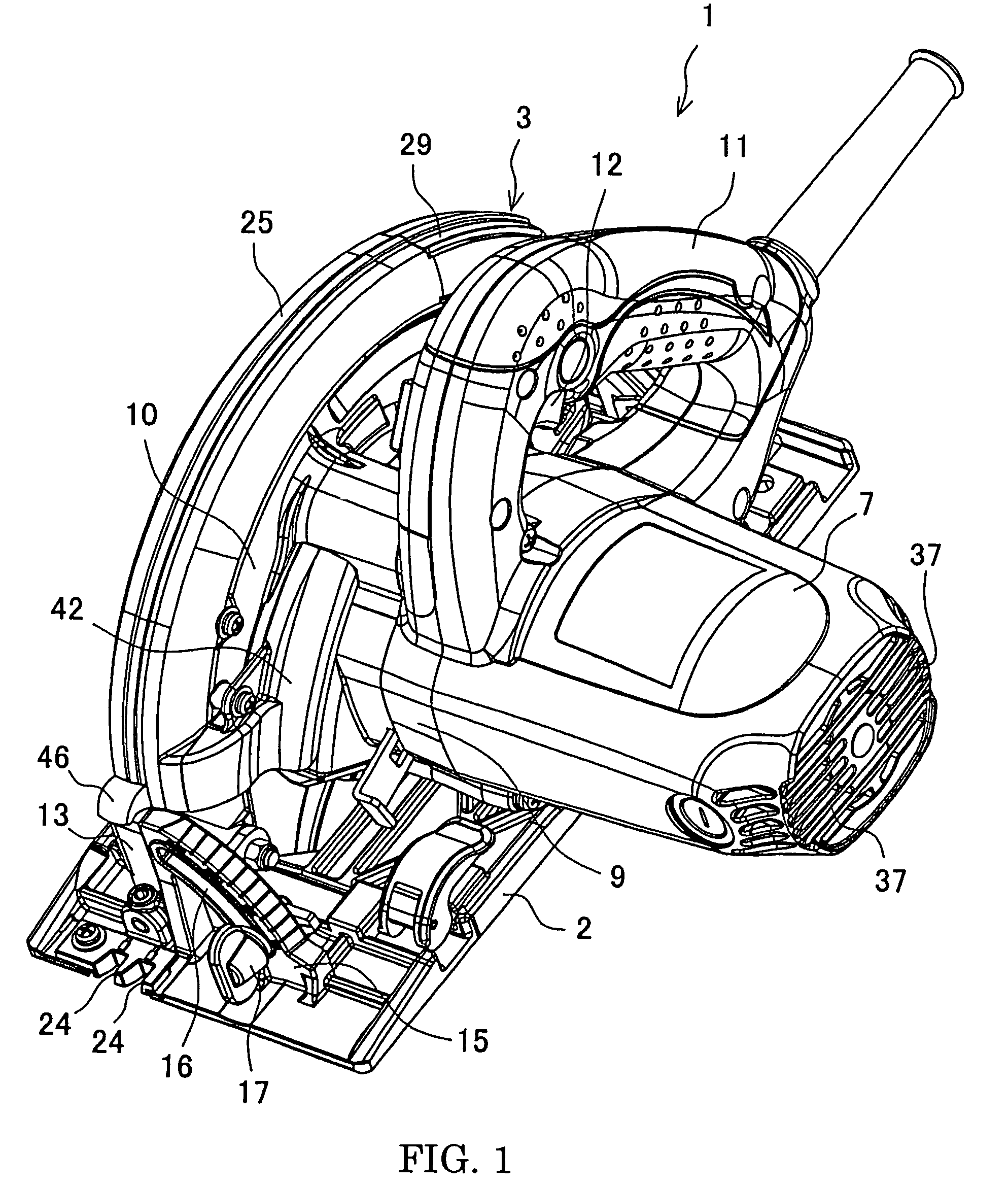
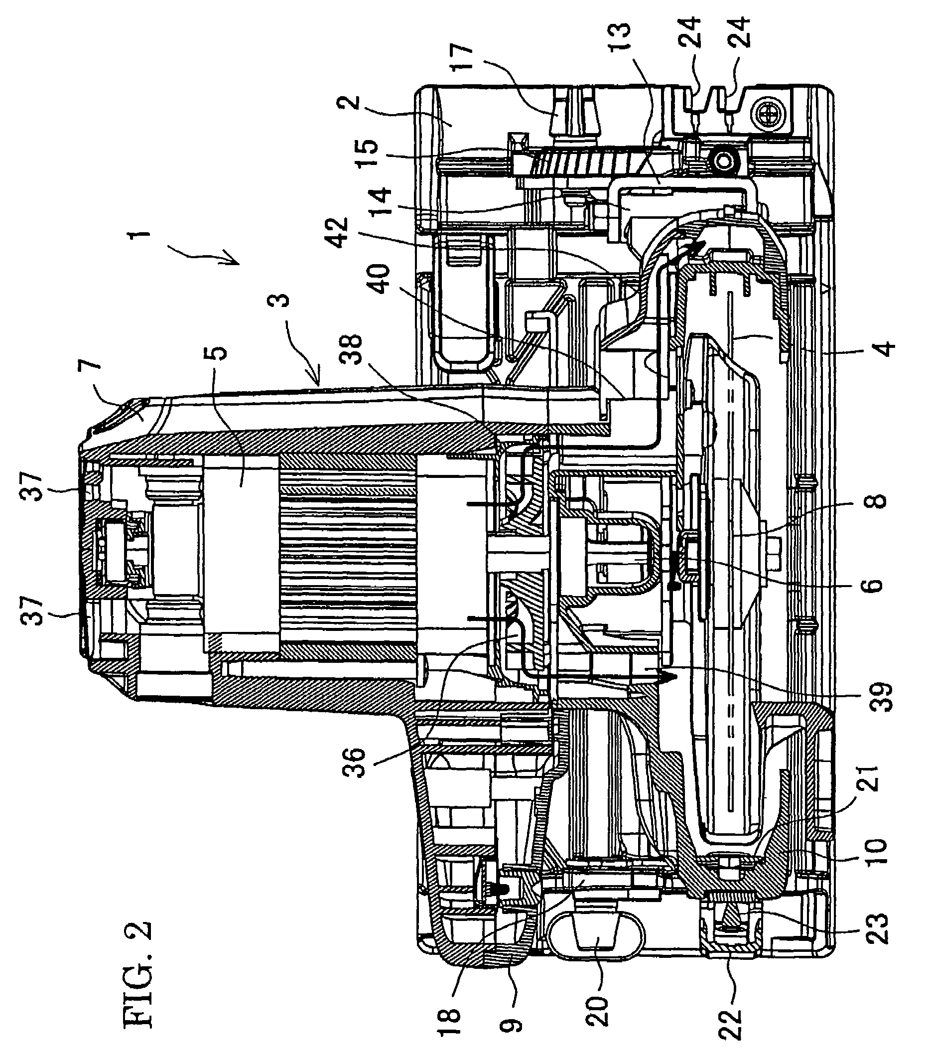
[0026]FIG. 1 is a schematic view of a circular saw as one example of a cutting tool according to the present invention and FIG. 2 is a horizontal sectional view thereof. A circular saw 1 described herein has a base 2 which is rectangular in a plain view and a main body 3 provided on the base 2 and having a circular saw blade 4 as a cutting blade driven to rotate by a motor 5. The main body 3 includes a motor housing 7 accommodating the motor 5, a handle housing 9 in conjunction with the motor housing 7 to form a handle 11, and a blade case 10 covering the upper part of the saw blade 4. The blade 4 is connected orthogonally to the end of a spindle 8. The spindle 8 is pivotally supported in the blade case 10 so as to be parallel to an output shaft 6 of the motor 5 for transmitting the rotation from the output shaft 6. The reference number 12 denotes a trigger switch provided with the...


PUM

PropertyMeasurementUnit
tilting angleaaaaaaaaaa
angleaaaaaaaaaa
circumferenceaaaaaaaaaa

Abstract

A cutting tool that maintains a compact-sized main body without affecting the usability as well as the dust collecting operation is provided. In a dust cover mounted on a blade case, a dust collection route divided from a saw blade is formed, and an outlet is provided at the rear side of the blade case in the cutting direction. Moreover, the blade case includes a peripheral surface in which an inlet and an auxiliary inlet are provided for guiding air generated by the rotation of the saw blade into the dust collection route from the front side in the cutting direction. Further, a guiding route where a part of cooling air for the motor is introduced into the dust collection route by means of a duct is provided, whereby the cooling air as well as air guided from the inlet is introduced into the dust collection route.

Description

BACKGROUND OF THE INVENTION[0001]This application claims the benefit of Japanese Patent Application Number 2004-277886 filed on Sep. 24, 2004, the entirety of which is incorporated by reference.[0002]1. Field of the invention[0003]The present invention relates to a cutting tool, such as a cutter which cuts a workpiece with a circular cutting blade or a circular saw.[0004]2. Description of the Related Art[0005]A conventional circular saw has a base which is rectangular in a plain view and a main body provided on the base and having a circular saw blade (cutting blade) driven to rotate by a motor. With a condition that the saw blade protrudes below the base, the base is slid on the workpiece, whereby the workpiece is cut by the saw blade. In this circular saw the front end of a blade case covering the upper part of the saw blade is rotatably mounted to the base. On the other hand, the rear end of the blade case can be fixed at an arbitrary position along an arcuate depth guide standin...

Claims


Application Information

Patent Timeline
Patent Type & Authority Patents(United States)
IPC IPC(8): B23D47/02
CPCB23D59/006B23D59/02Y10T83/207Y10T83/283Y10T83/929
Inventor YOSHIMURA, TAKAYOSHINASHIMOTO, TOMONOBUWADA, YUKIMATSUBARA, KOUJI
Owner MAKITA CORP
Learn More