
Reverse operation of a vehicle

Active Publication Date: 2008-06-03
BOMBARDIER RECREATIONAL PROD INC
View PDF46 Cites 12 Cited by
  • Summary
  • Abstract
  • Description
  • Claims
  • Application Information

AI Technical Summary

Benefits of technology

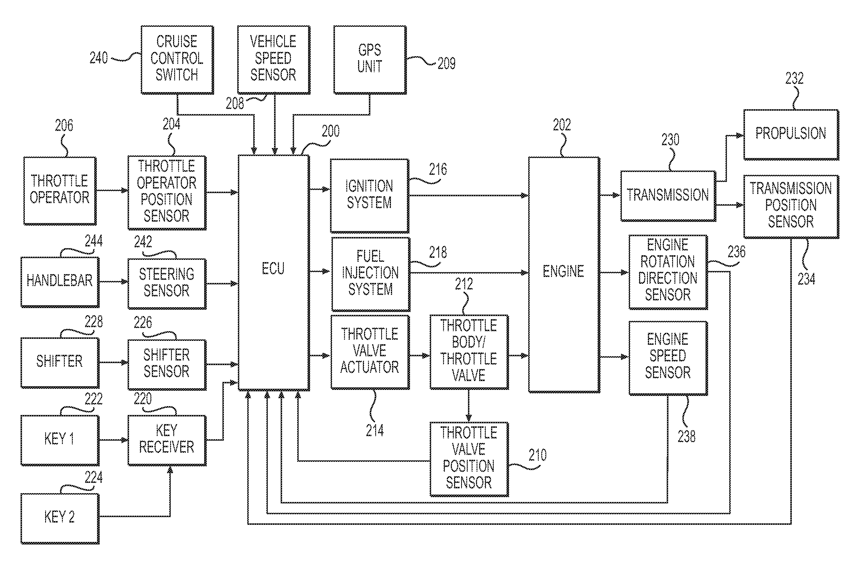
[0016]It is also an object of the present invention to provide a vehicle that has an ECU that controls an engine of the vehicle by sending a control signal to a throttle valve actuator such that the vehicle does not exceed a predetermined maximum vehicle speed when moving in a reverse direction.
[0054]In another aspect, the invention provides a vehicle having a vehicle body and a seat associated with the vehicle body. An engine is associated with the vehicle body for powering the vehicle. The engine has at least one combustion chamber. An electronic control unit on the vehicle controls an operation of the engine. A throttle body is in fluid communication with the at least one combustion chamber. A throttle valve is disposed in the throttle body for controlling an amount of air supplied to the at least one combustion chamber. A throttle valve actuator is operatively connected to the throttle valve and is in electronic communication with the ECU. A throttle operator is disposed on the vehicle in proximity to the seat. A throttle operator position sensor senses a throttle operator position and is in electronic communication with the ECU for sending a signal representative of a throttle operator position to the ECU. A shifter is disposed on the vehicle in proximity to the seat for selecting a vehicle operation direction between a forward direction and a reverse direction. A vehicle speed sensor senses a vehicle speed and is in electronic communication with the ECU for sending a signal representative of a vehicle speed to the ECU. A vehicle operation direction sensor senses the vehicle operation direction and is in electronic communication with the ECU for sending a signal representative of a vehicle operation direction to the ECU. The ECU sends a control signal to the throttle valve actuator based on the throttle operator position signal, the vehicle speed signal, and the vehicle operation direction signal. The throttle valve actuator adjusts a degree of opening of the throttle valve in response to the control signal. When the vehicle operation direction is the forward direction, the control signal causes the throttle valve actuator to adjust the degree of opening of the throttle valve based on the throttle operator position when the vehicle speed is lower than a predetermined maximum forward vehicle speed and causes the throttle valve actuator to reduce the degree of opening of the throttle valve when the vehicle speed is higher than the predetermined maximum forward vehicle speed. When the vehicle operation direction is the reverse direction, the control signal causes the throttle valve actuator to adjust the degree of opening of the throttle valve based on the throttle operator position signal up to a maximum degree of opening of the throttle valve.

Problems solved by technology

For example, in the case of an ATV moving on a level surface, opening the throttle valve results in the ATV accelerating and closing the throttle valve results in the ATV decelerating.
This control strategy results however in a rough engine operation which is undesirable.
This greatly improves the control of the engine, however controlling the engine based on the engine speed may not be ideal in some instances.
This causes a reduced performance of the personal watercraft when the load is increased (driver with passengers for example) since it will have a lower maximum speed than when a lighter load is present (only the driver for example).
However, this method may not be applicable to every type of vehicle, such as personal watercraft given their lack of brakes.
However, such transmissions can be complex and add substantial weight to the vehicle, especially for vehicles using a continuously variable transmission (CVT).

Method used


Image

  • Reverse operation of a vehicle
  • Reverse operation of a vehicle
  • Reverse operation of a vehicle

Examples


Embodiment Construction

[0078]The present invention will be described with respect to vehicles having a single throttle body, a single throttle valve, and a single throttle valve actuator, but it should be understood that vehicles having multiple throttle bodies and throttle valves with one or more throttle valve actuators are also contemplated.

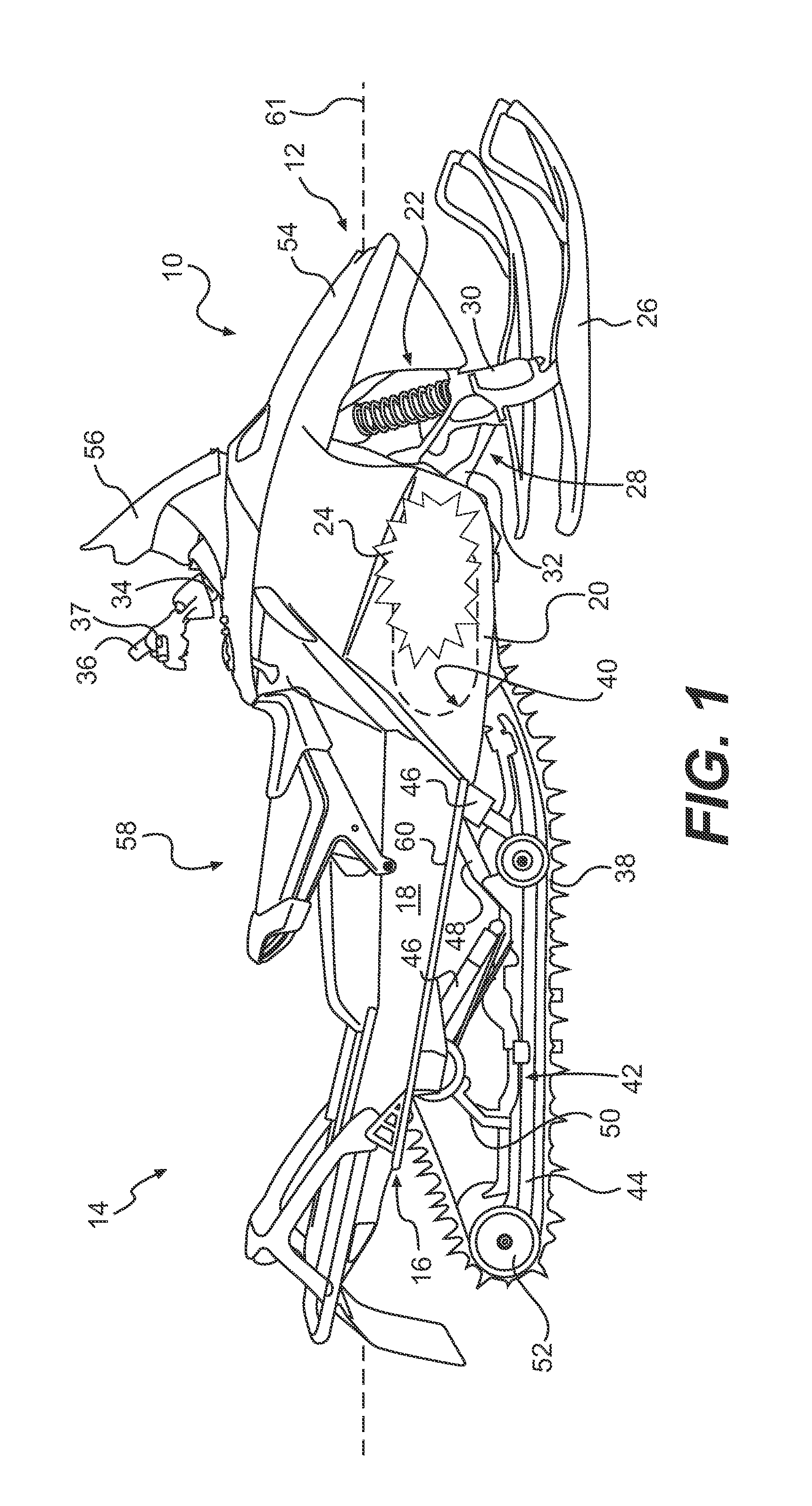
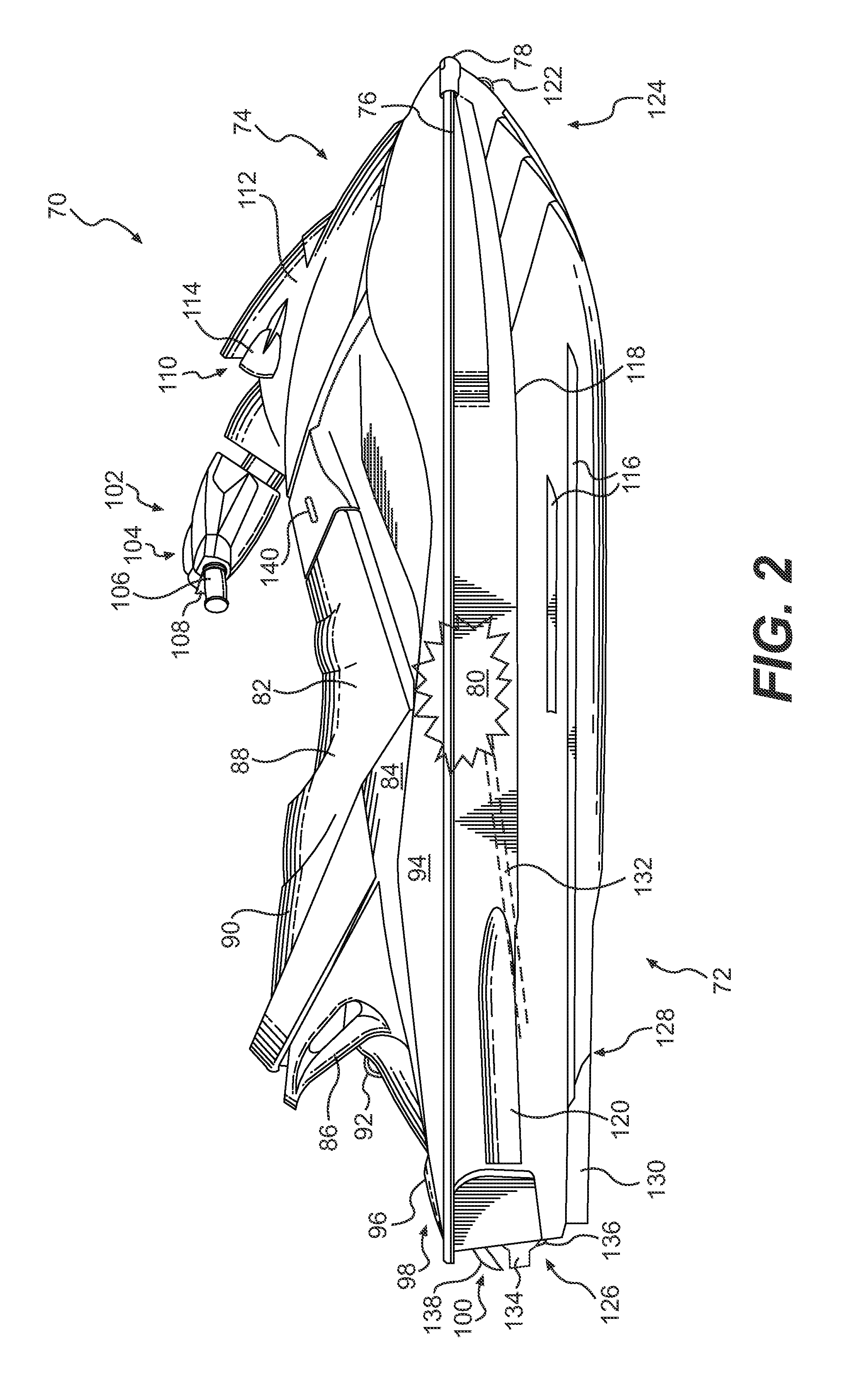
[0079]The present invention will also be described with respect to a snowmobile 10, a personal watercraft 70, and an ATV 150, but it should be understood that aspects of the invention could also be used on other types of vehicles such as boats, motorcycles, or engine-powered tricycles. Each of those vehicles will now be described.

[0080]Referring to FIG. 1, a snowmobile 10 includes a forward end 12 and a rearward end 14 which are defined consistently with a travel direction of the vehicle. The snowmobile 10 includes a vehicle body in the form of a frame or chassis 16 which normally includes a rear tunnel 18, an engine cradle portion 20 and a front suspension assembly...


PUM


Abstract

A vehicle has a vehicle body, a seat, an engine, an ECU, a throttle body, a throttle valve, a throttle valve actuator, a throttle operator, and a throttle operator position sensor. A shifter is disposed on the vehicle in proximity to the seat for selecting a vehicle operation direction between a forward direction and a reverse direction. A vehicle operation direction sensor senses the vehicle operation direction. The ECU limits a maximum speed of the vehicle when it operates in the reverse direction. In another aspect, the ECU limits the degree of opening of the throttle valve when it operates in the reverse direction. Methods of controlling an engine are also disclosed.

Description

CROSS-REFERENCE[0001]The present application claims priority to U.S. Provisional Patent Application No. 60 / 871,684, filed Dec. 22, 2006, entitled “Throttle-By-Wire System”, the entirety of which is enclosed herewith.FIELD OF THE INVENTION[0002]The present invention relates to an engine control method and a vehicle having an engine controlled by the method.BACKGROUND OF THE INVENTION[0003]Most recreational vehicles, such as all-terrain vehicles (ATVs), snowmobiles, and personal watercraft, are powered by an internal combustion engine. The operation of the engine generally is controlled by adjusting the quantity of air and fuel the combustion chambers of the engine receive, and by controlling the timing of the ignition of the air / fuel mixture in the combustion chamber. In the case of fuel injected engines, the timing of the injection of the fuel can also be controlled.[0004]Recreational vehicles typically have one or more throttle valves in the engine's air intake system which are mec...

Claims


Application Information

Patent Timeline
IPC IPC(8): F02D41/00F16H59/52
CPCB60K31/04F02D31/006F02D41/0225B60W2300/362B60W2300/43Y10T477/65F02D2250/06B60W2520/06B60W30/146
Inventor GAGNON, MARCDAUNAIS, JEAN
Owner BOMBARDIER RECREATIONAL PROD INC
Learn More