Displacement control mechanism for variable displacement compressor

a variable displacement compressor and displacement control technology, which is applied in the direction of machines/engines, positive displacement liquid engines, lighting and heating apparatus, etc., can solve the problems of undesirable operation of variable displacement compressors at high rotation speed and high displacement, and achieve the effect of increasing an opening degree and decreasing the opening degr

Inactive Publication Date: 2009-07-14
TOYOTA IND CORP +1
View PDF8 Cites 8 Cited by
  • Summary
  • Abstract
  • Description
  • Claims
  • Application Information

AI Technical Summary

Benefits of technology

[0008]According to the present invention, a displacement control mechanism is used for a variable displacement compressor, which adjusts a pressure in a pressure control chamber by introducing a refrigerant in a discharge pressure region into the pressure control chamber through a supply passage and releasing the refrigerant in the pressure control chamber to a suction pressure region through a bleed passage, thereby controlling displacement of the compressor. The displacement control mechanism includes a first valve hole, a first valve body, a pressure sensing means and a pressure-difference-increasing means. The first valve hole partially forms the supply passage or the bleed passage. The first valve body is operable to open and close the first valve hole. The pressure sensing means operable to sense a pressure of a first point in the discharge pressure region and a pressure of a second point in the discharge pressure region and to adjust a position of the first valve body based on pressure difference between the first and second points. The pressure-difference-increasing means is operable to increase the pressure difference between the first and second points when the pressure of the suction pressure region falls below a predetermined standard pressure. The pressure sensing means displaces the first valve body in such a direction so as to increase an opening degree of the first valve hole according to increase of the pressure difference when the first valve hole is a part of the supply passage. The pressure sensing means displaces the first valve body in such a direction so as to decrease the opening degree of the first valve hole according to the increase of the pressure difference when the first valve hole is a part of the bleed passage.

Problems solved by technology

Such high rotation speed of the rotary shaft and large displacement operation produce a great load acting on the compressor, more particularly on the swash plate, which is undesirable in view of reliable operation.
Even if the refrigerant gas is sufficient in the variable displacement compressor, the operation of the variable displacement compressor at high rotation speed and at high displacement is undesirable in view of reliable operation In the variable displacement compressor including the hinge mechanism as disclosed in Unexamined Japanese Patent Publication No 2004-108245. the inclination angle of the swash plate may exceed the predetermined maximum inclination angle because of a great inertial force of the piston.

Method used


Image

  • Displacement control mechanism for variable displacement compressor
  • Displacement control mechanism for variable displacement compressor
  • Displacement control mechanism for variable displacement compressor

Examples


Embodiment Construction

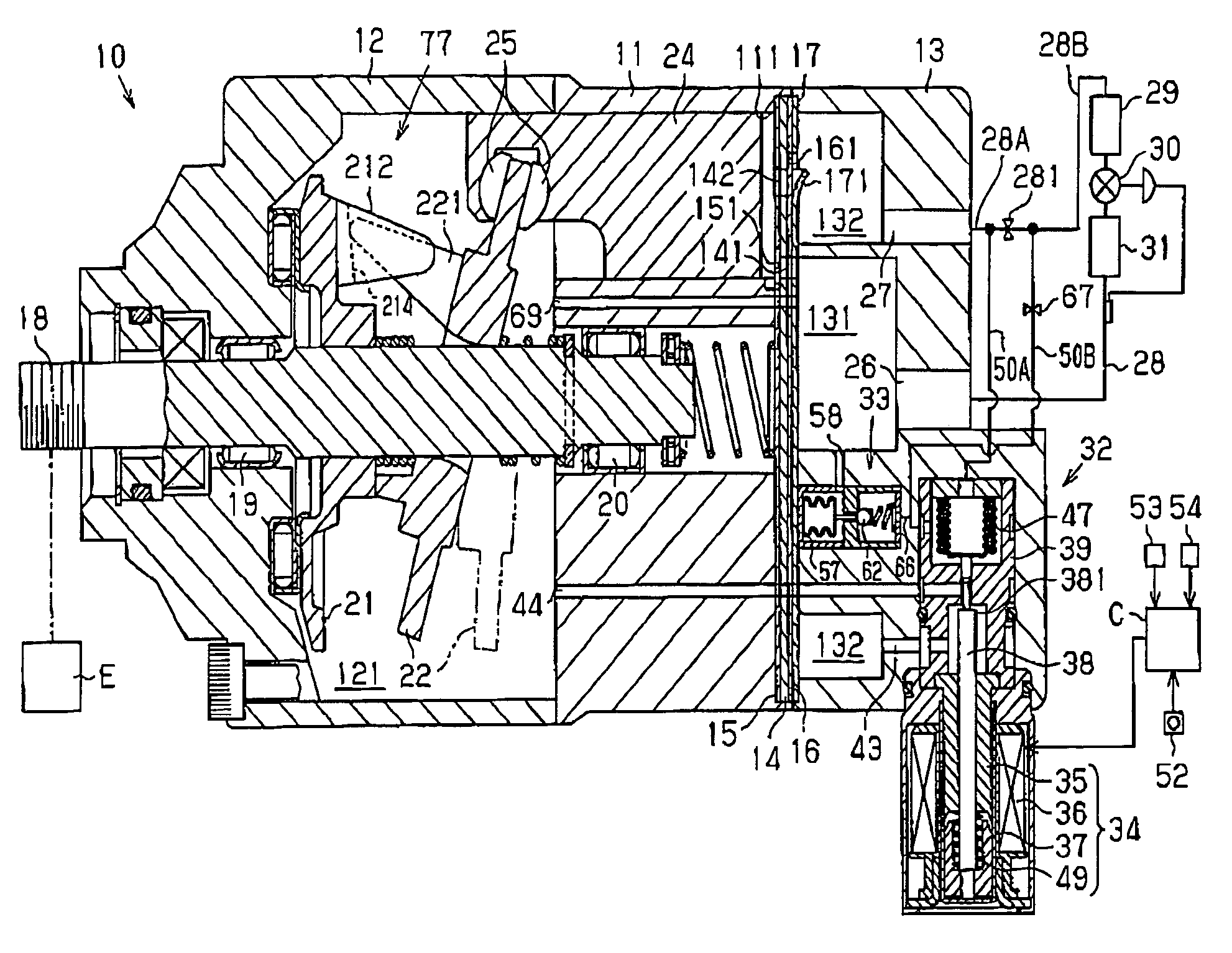
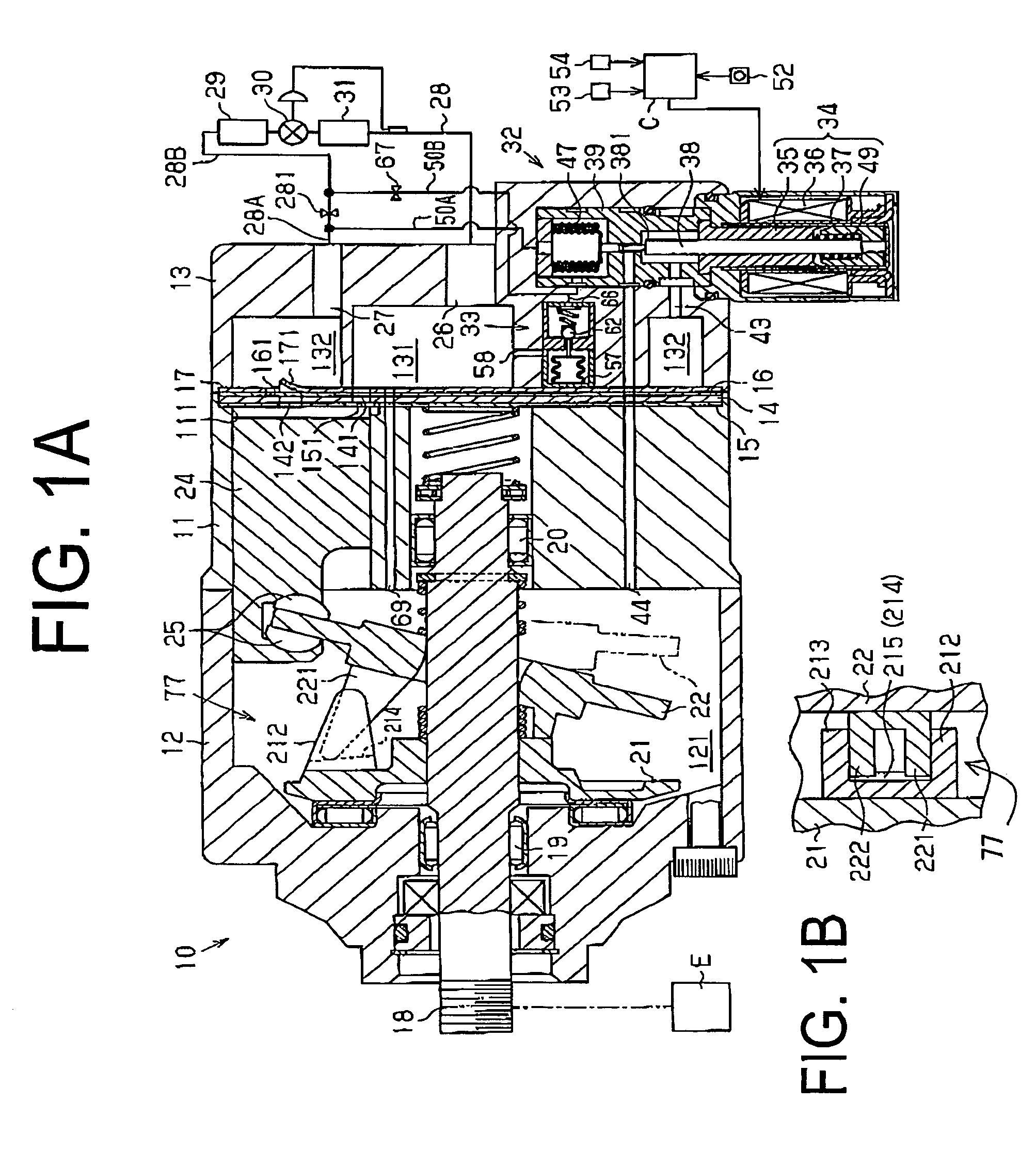
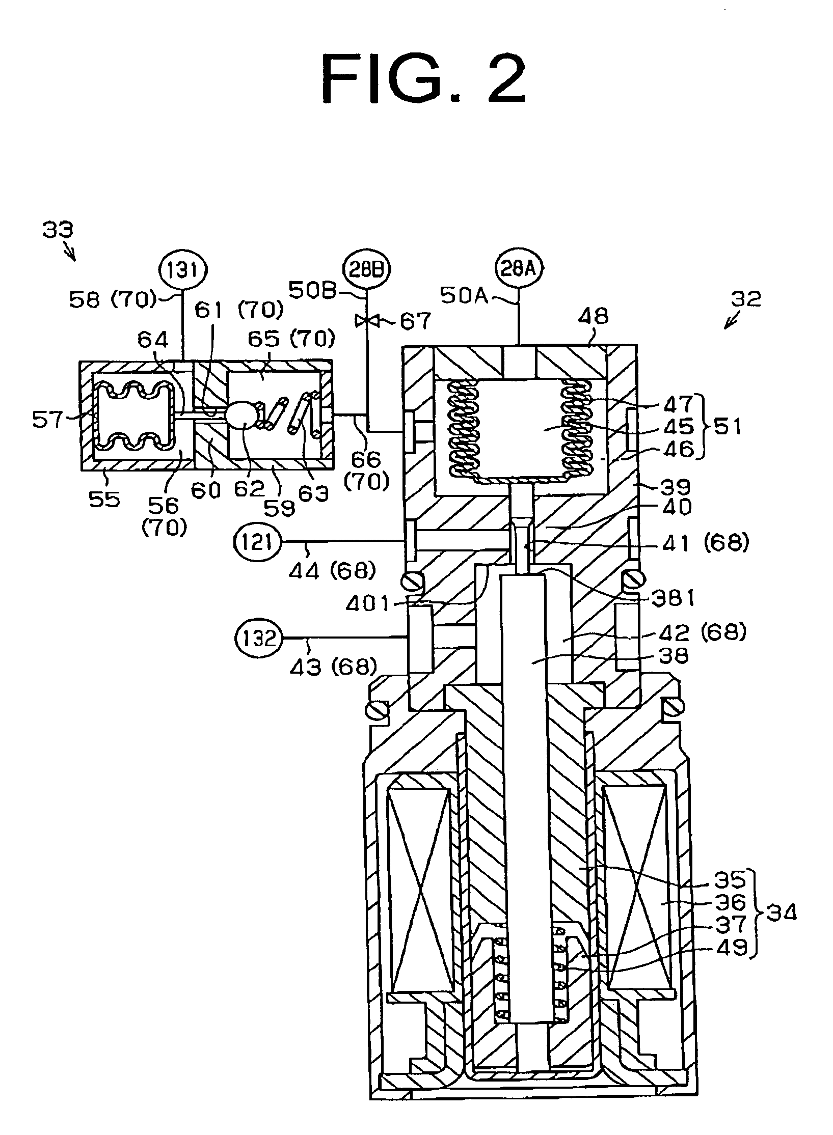
[0015]The following will describe a first preferred embodiment according to the present invention with reference to FIGS. 1A through 2. As shown in FIG. 1A, a variable displacement compressor 10 has a housing assembly including a cylinder block 11, a front housing 12 and a rear housing 13. The front housing 12 is connected to the front end (the left end as seen in FIG. 1) of the cylinder block 11. The rear housing 13 is connected to the rear end (the right end as seen in FIG. 1) of the cylinder block 11 through a valve plate 14, valve plate forming plates 15 and 16 and a retainer forming plate 17.

[0016]The front housing 12 and the cylinder block 11 cooperate to define a pressure control chamber 121 through which a rotary shaft 18 extends. The rotary shaft 18 is supported by the front housing 12 and the cylinder block 11 via radial bearings 19 and 20. The rotary shaft 18 projects from the pressure control chamber 121 to the outside of the compressor 10 and is driven to rotate by a ve...


PUM


Abstract

A displacement control mechanism for a variable displacement compressor includes a first valve hole, a first valve body, a pressure sensing means operable to sense pressures of first and second points in a discharge pressure region to adjust a position of the first valve body, and a pressure-difference-increasing means operable to increase pressure difference between the first and second points when the pressure of a suction pressure region falls below a predetermined standard pressure. The pressure sensing means displaces the first valve body to increase an opening degree of the first valve hole according to increase of the pressure difference when the first valve hole is part of a supply passage. The pressure sensing means displaces the first valve body to decrease the opening degree of the first valve hole according to the increase of the pressure difference when the first valve hole is part of a bleed passage.

Description

BACKGROUND OF THE INVENTION[0001]The present invention relates to a displacement control valve used for a variable displacement compressor that adjusts the pressure in a pressure control chamber by introducing a refrigerant in the discharge pressure region of the compressor into the pressure control chamber through a supply passage and releasing the refrigerant in the pressure control chamber to the suction pressure region of the compressor through a bleed passage, thereby controlling displacement of the compressor.[0002]In a variable displacement compressor having a pressure control chamber that accommodates a swash plate whose inclination angle is variable, the inclination angle of the swash plate decreases as the pressure in the pressure control chamber rises. This decrease of the inclination angle increases the stroke of a piston, thereby to increase the displacement of the compressor. On the other hand, the inclination angle of the swash plate increases as the pressure in the p...

Claims


Application Information

Patent Timeline
Patent Type & Authority Patents(United States)
IPC IPC(8): F04B1/29
CPCF04B27/1036F04B27/1804F04B49/225F04B2027/1859F04B2027/1813F04B2027/1827
Inventor OTA, MASAKIUMEMURA, SATOSHIKAWAGUCHI, MASAHIROHIBINO, SOKICHI
Owner TOYOTA IND CORP
Why Eureka
Try Eureka