Brake negative pressure control device for vehicle

a control device and negative pressure technology, applied in the direction of electric control, braking system, combustion air/fuel air treatment, etc., can solve the problems of insufficient intake negative pressure, inability to secure brake negative pressure, so as to reduce the insufficiency of negative pressure, increase the cooling effect of intake air, and reduce the effect of negative pressur

Inactive Publication Date: 2017-06-15
TOYOTA JIDOSHA KK
View PDF0 Cites 7 Cited by
  • Summary
  • Abstract
  • Description
  • Claims
  • Application Information

AI Technical Summary

Benefits of technology

[0016]In the brake negative pressure control device according to the aspect, the brake booster may include a negative pressure pump. The negative pressure pump may be connected to the negative pressure chamber so as to create a negative pressure to the negative pressure chamber. The electronic control unit may be configured to determine that the negative pressure is insufficient, when the negative pressure pump has a failure. According to the brake negative pressure control device according to the aspect, when a sufficient pump negative pressure cannot be supplied to the brake booster due to the failure of the negative pressure pump and the negative pressure is insufficient, it is possible to restrain the insufficiency of the negative pressure.
[0017]In the brake negative pressure control device according to the aspect, the electronic control unit may be configured to control the second fuel injection valve when the electronic control unit determines that the negative pressure is insufficient, such that a fuel injection start timing by the second fuel injection valve is set to a retard side relative to a predetermined timing. In the brake negative pressure control device according to the aspect, the fuel injection by the second fuel injection valve is performed in an intake stroke of the cylinder in general, but when its start timing is set to the retard side relative to the predetermined timing (e.g., 60° to 90° CA after an intake-air top dead center), an adherence amount of fuel spray to a piston decreases, thereby making it possible to further increase a cooling effect of the intake air.
[0018]In the brake negative pressure control device according to the aspect, the electronic control unit may be configured to control the engine when the electronic control unit determines that the negative pressure is insufficient, such that a pressure of fuel injection by the second fuel injection valve is set to be higher than a predetermined value. According to the brake negative pressure control device according to the aspect, atomization of the fuel spray injected into the cylinder from the second fuel injection valve is promoted, so that the cooling effect of the intake air further increases. Note that, as the fuel injection pressure is higher, it is possible to promote the atomization of the fuel spray more. However, there is such a possibility that an increase in spray penetration along with this may cause an increase in an adherence amount of the fuel spray to the piston. In view of this, the predetermined value should be set in consideration for the influence of both.
[0019]As described above, according to the brake negative pressure control device for the vehicle, according to one aspect of the present disclosure, in the engine configured to inject the fuel into both the intake passage and the cylinder, when the negative pressure to be supplied to the brake booster is insufficient, the ratio of the fuel injection into the cylinder is increased so that the charging efficiency of the intake air is improved, and the opening degree of the throttle valve is decreased by just that much. Hereby, the intake negative pressure can be increased and a sufficient assist force can be obtained by the brake booster. Besides, even if the opening degree of the throttle valve is decreased for that purpose, the torque of the engine can be maintained, thereby preventing a decrease in drivability.

Problems solved by technology

However, the intake negative pressure is not so large, so a sufficient brake negative pressure may not be able to be secured in some cases.
However, the fuel cut is not necessarily performed when it is necessary to increase the intake negative pressure, so such a situation in which the intake negative pressure is insufficient may occur.
However, in this case, there is such a concern that the brake negative pressure cannot be secured due to a failure of the vacuum pump.
As a result, a torque of the engine tends to increase, but the opening degree of the throttle valve is decreased, thereby reducing the increase in the torque.
However, there is such a possibility that an increase in spray penetration along with this may cause an increase in an adherence amount of the fuel spray to the piston.

Method used


Image

  • Brake negative pressure control device for vehicle
  • Brake negative pressure control device for vehicle
  • Brake negative pressure control device for vehicle

Examples


Embodiment Construction

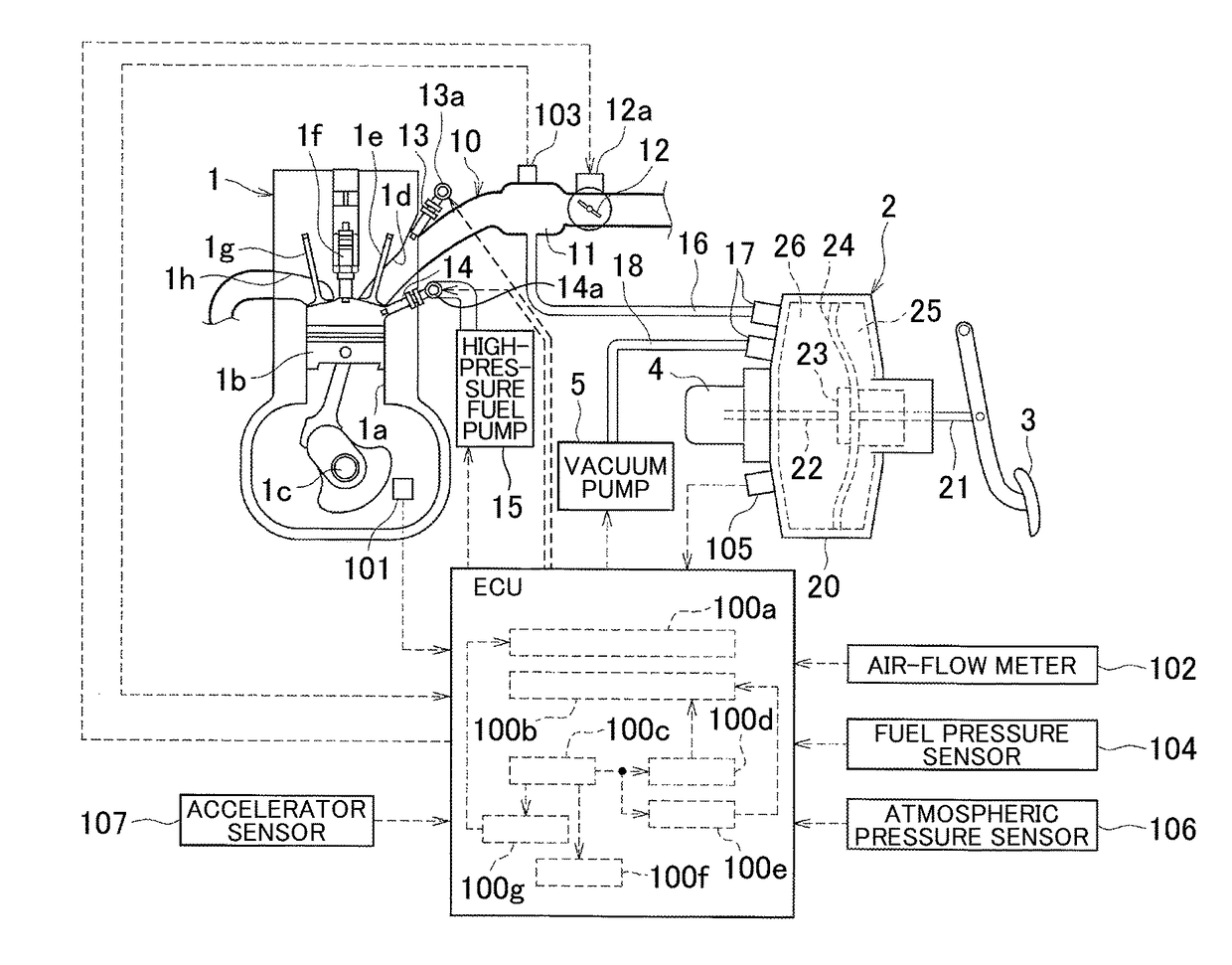
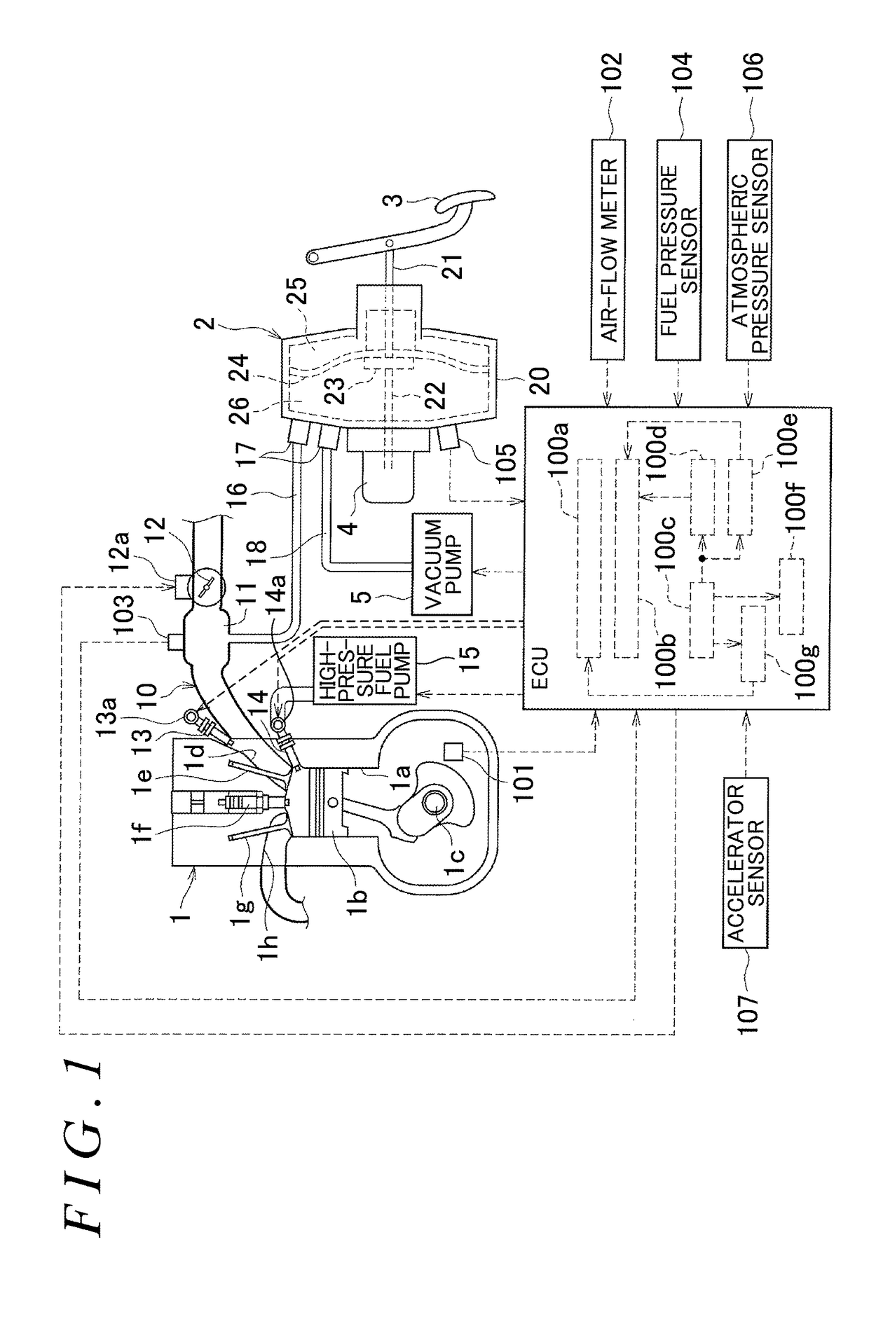
[0026]A brake negative pressure control device according to an embodiment of the present disclosure will be described below with reference to the drawings. First, as schematically illustrated in FIG. 1, a braking system according to the present embodiment is configured to supply, to a brake booster 2, a negative pressure (an intake negative pressure) of an intake passage 10 of an engine 1 provided in a vehicle (not shown) and a negative pressure (a pump negative pressure) generated by a vacuum pump 5 (a negative pressure pump).

[0027]Schematic Configuration of Engine—In the present embodiment, the engine 1 is a gasoline engine, for example, and as schematically illustrated in FIG. 1, respective pistons 1b (only one of them is illustrated in the figure) accommodated in a plurality of cylinders 1a are connected to a crankshaft 1c via respective connecting rods. A crank angle sensor 101 for detecting a turning angle (a crank angle) of the crankshaft 1cis disposed in the vicinity of the ...


PUM


Abstract

A brake negative pressure control device for a vehicle includes an ECU. The ECU is configured to (i) control a first fuel injection valve and a second fuel injection valve, when the ECU determines that a negative pressure in a negative pressure chamber is insufficient, such that a ratio of a fuel injection amount by the first fuel injection valve is decreased and a ratio of a fuel injection amount by the second fuel injection valve is increased; and (ii) control an opening degree of the throttle valve, when the ECU determines that the negative pressure in the negative pressure chamber is insufficient, such that the opening degree of the throttle valve at the time when the ECU determines that the negative pressure is insufficient is smaller than an opening degree of the throttle valve at the time when the ECU determines that the negative pressure is not insufficient.

Description

INCORPORATION BY REFERENCE[0001]The disclosure of Japanese Patent Application No. 2015-243362 filed on Dec. 14, 2015 including the specification, drawings and abstract is incorporated herein by reference in its entirety.BACKGROUND[0002]1. Technical Field[0003]The present disclosure relates to a device for controlling an intake negative pressure of an engine to be supplied to a brake booster of a vehicle, and particularly, belongs to a technical field of a control to increase the intake negative pressure.[0004]2. Description of Related Art[0005]Conventionally, a braking system of a vehicle is generally configured to supply a negative pressure (an intake negative pressure) of an intake passage in an engine to a brake booster, thereby generating an assist force to amplify a brake pedal force. For example, a cylinder injection engine described in Japanese Patent Application Publication No. 2001-182587 (JP 2001-182587 A) focuses on a fact that an intake negative pressure is very small (a...

Claims


Application Information

Patent Timeline
Patent Type & Authority Applications(United States)
IPC IPC(8): B60T13/72F02D9/02F02D41/30B60T13/52
CPCB60T13/72B60T13/52F02D2250/41F02D41/3094F02D9/02F02D9/08F02D37/00F02D41/36F02D41/38F02D41/401F02D2041/389F02D2200/50B60T17/02F02D41/0002F02M35/10229Y02T10/40
Inventor FUJITA, YASUSHI
Owner TOYOTA JIDOSHA KK
Why Eureka
Try Eureka