EGR cooler with dual coolant loop

a dual-loop, cooler technology, applied in the direction of machines/engines, laminated elements, lighting and heating apparatus, etc., can solve the problems of less heat exchange effect and cooler temperature over the length of the cooler

Inactive Publication Date: 2008-06-03
MODINE MFG CO
View PDF12 Cites 71 Cited by
  • Summary
  • Abstract
  • Description
  • Claims
  • Application Information

AI Technical Summary

Problems solved by technology

This raises the coolant temperature and makes the heat exchange less effective over the length of the cooler as the differential temperature between the coolant and exhaust gases become smaller.

Method used


Image

  • EGR cooler with dual coolant loop
  • EGR cooler with dual coolant loop
  • EGR cooler with dual coolant loop

Examples


Embodiment Construction

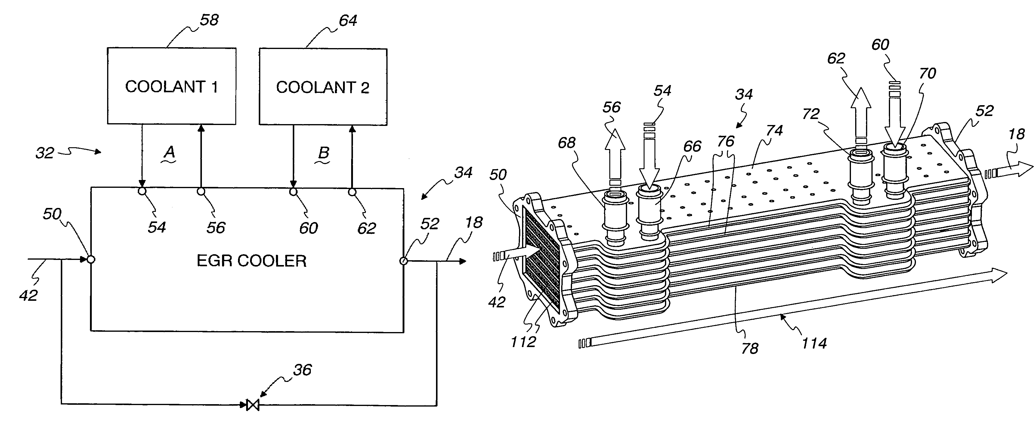
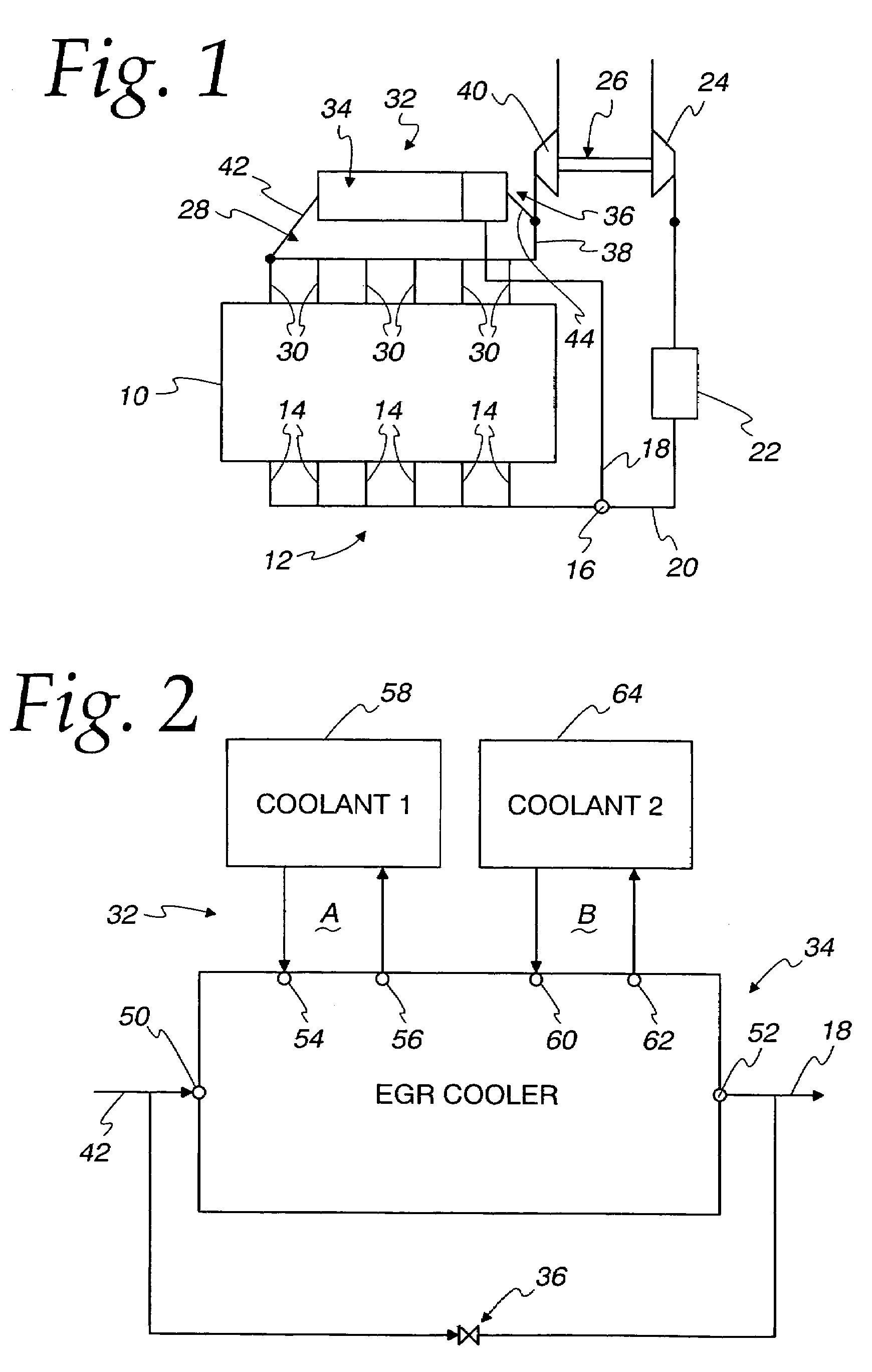
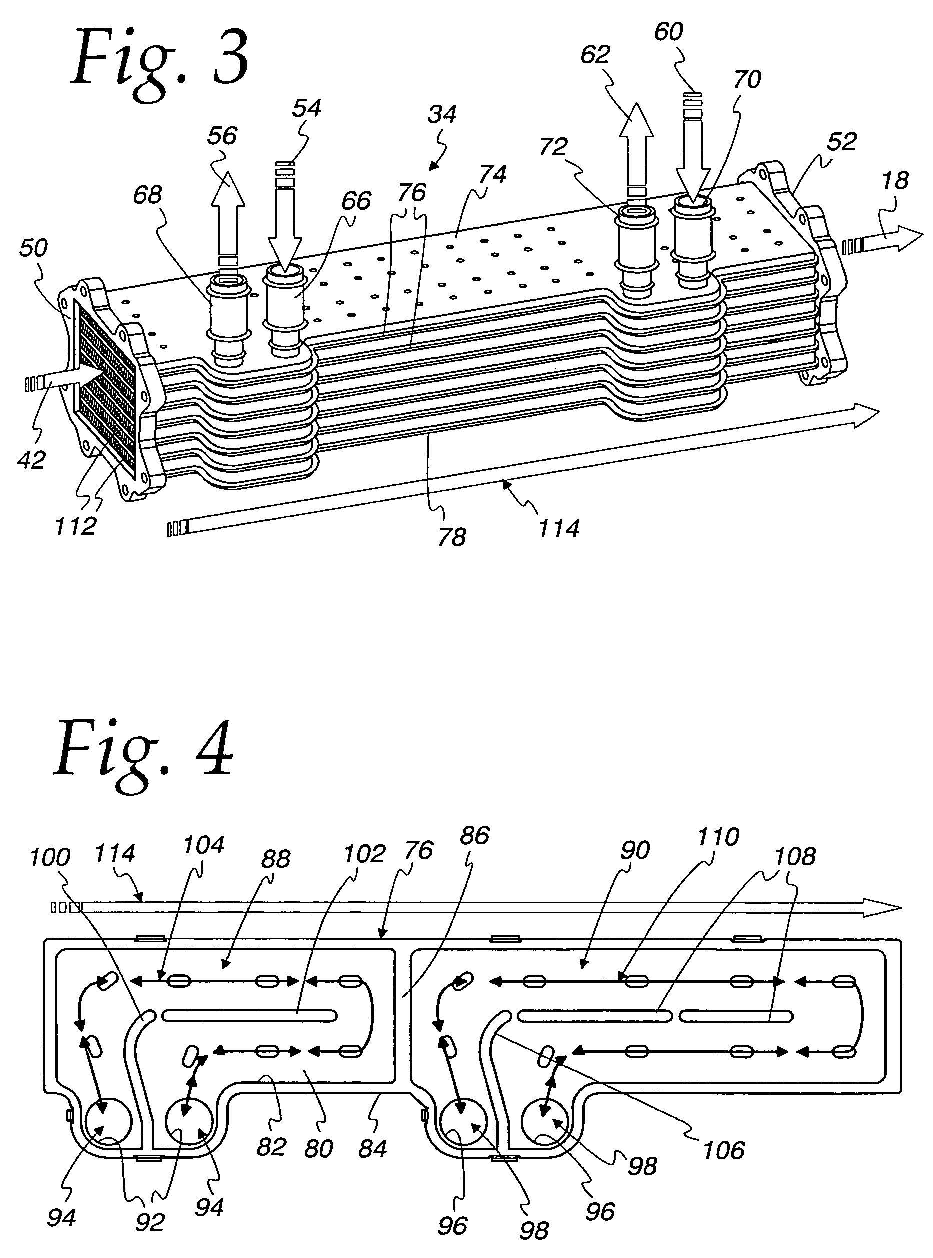
[0021]Referring first to FIG. 1, an exemplary embodiment of an exhaust gas heat exchange system made according to the invention is described. The invention is described in the environment in which a typical diesel engine for a truck-like vehicle operates but it is to be understood that the invention is applicable to internal combustion engines other than diesel engines and may be employed in stationary engine applications as well as applications for engines other than trucks, as, for example, automobiles and construction, excavating, power generation, marine applications and others.

[0022]A six cylinder diesel engine is generally designated 10 and includes an intake manifold 12 having outlet connections 14 to each of the cylinders of the engine 10. The intake manifold 12 includes an inlet 16 for receiving recirculated exhaust gas from an exhaust gas recirculation line 18 as well as combustion air from a line 20. While a single inlet is illustrated, two separate inlets could be employ...


PUM


Abstract

An integrated exhaust gas recirculation (EGR) cooler with dual coolant loops comprises an exhaust gas inlet and an exhaust gas outlet for recirculating exhaust gas. An exhaust gas flow path extends between the exhaust gas inlet and the exhaust gas outlet to direct recirculating exhaust gas from the exhaust gas inlet to the exhaust gas outlet. A first coolant flow path extends between a first coolant inlet and a first coolant outlet to direct a first coolant flow from the EGR cooler in heat exchange relation with the exhaust gas flow path. A second coolant flow path extends between a second coolant inlet and a second coolant outlet to direct a second coolant flow through the EGR cooler in heat exchange relation with the exhaust gas flow path.

Description

CROSS REFERENCE TO RELATED APPLICATIONS[0001]There are no related applications.FIELD OF THE INVENTION[0002]This invention relates to an exhaust gas recirculation cooler and, more particularly, the use of integrated dual coolant loops for cooling recirculating exhaust gas.BACKGROUND OF THE INVENTION[0003]Emission concerns associated with the operation of internal combustion engines, generally, but not always, diesel engines, have resulted in an increased emphasis on the use of exhaust gas heat exchange systems with such engines, particularly, but not always, in vehicular applications. These systems are employed as part of an exhaust gas recirculation (EGR) system by which a portion of an engine's exhaust is returned to its combustion chambers via its intake system. The result is that some of the oxygen that would ordinarily be inducted into the engine as part of its fresh combustion air charge is displaced with inert gases thus reducing the rate of NOx formation. EGR systems are freq...

Claims


Application Information

Patent Timeline
Patent Type & Authority Patents(United States)
IPC IPC(8): F02M25/07F02B47/08F28F3/00F02B33/44
CPCF28D9/0056F28D9/0093F02M25/0737F02B29/0406F02B37/00F02M25/0707F02M25/0728Y02T10/121F28D21/0003F02M26/05F02M26/25F02M26/32Y02T10/12F01N3/02
Inventor RADUENZ, DAN R.MESHENKY, STEVEN P.
Owner MODINE MFG CO
Why Eureka
Try Eureka