Rotatable cutting tool having retainer with dimples

a technology of rotating cutting tools and retainers, which is applied in the direction of cutting machines, cutting machines, earthwork drilling and mining, etc., can solve the problems of reducing affecting the service life of the retainer, so as to prevent the axial removal improve the attachment of the cutting bit, and resist the

Active Publication Date: 2008-06-03
KENNAMETAL INC
View PDF49 Cites 41 Cited by
  • Summary
  • Abstract
  • Description
  • Claims
  • Application Information

AI Technical Summary

Benefits of technology

[0014]An object of the invention is to prevent fracture / crack propagation adjacent the shear cut lines of the stop tab openings on a retainer. The applicant's invention positions the shank so that the shank hub contacts the retainer axially rearward and away from the weak shear cut lines of the retainer from which cracks propagate in the prior art. The retainer of applicant's invention includes stop tab tips beyond the shear cut lines of the tab opening so that the hub portions of the shank do not transmit a force against these weakened shear cut edges of the stop tab openings.
[0015]Another feature of the invention is the shear cut lines of the stop tab openings are rounded to prevent stress concentration of loads as occur in sharp angled corner openings.
[0018]Another alternative embodiment has a shank portion that includes an annular recessed groove, and the cylindrical bore has a notch corresponding to and disposed opposite the annular groove. The retainer has stop tabs that are received in the groove and dimples that are received in the bore notch. This invention improves attachment of the cutting bit within the bore of the bit holder and prevents axial removal of the cutting bit when in use while still allowing rotatable movement of the cutting bit within the bore.

Problems solved by technology

In these prior art designs the retainers often failed prematurely due to cracks and splits that developed at a shear cut edge at the axially rearward end of stop tab opening.
Such stop tab opening shear cut lines locally weakens the retainer's strength and resistance to fracture.
This contact in prior art designs applies a shearing force that is concentrated along the retainer opening and causes a propagating fracture.
Such designs are more likely to fracture / crack along the shear cut lines than along the other positions of the retainer.
The fracture of the retainer in the field causes difficulty in removing the retainer from the bit holder.
When an operator attempts to remove the retainer for replacement, it occasionally breaks off and additional time and tools are needed to remove the portion of the retainer remaining in the bit holder.
Fractured retainers make used tools difficult to remove or the retainer sticks in the bore and the tool shank is ejected without the retainer.
This creates production delays in changing the tool.
This additional downtime needed to remove fractured retainers increases required labor costs.
Retainer fracture and failure in the prior art is often attributed to relative axial movement between the retainer and cutting tool shank.
The amount of axial play of the cutting tool in prior art devices such as the embodiment in FIG. 6 of Hedlund increases during the lifetime of the tool on account of wear occurring to the stop fingers.
The premature wear and fracture of cylindrical retainers on cutting tool assemblies requires the cutting tool assemblies to be more frequently replaced and / or inspected.
Once the tool stops rotating the cutting tool bit becomes unevenly worn on one side and the cutting bit quickly becomes damaged and inoperative.
Some cutting bits are knocked out and become lost after the retainer is fractured or worn.

Method used


Image

  • Rotatable cutting tool having retainer with dimples
  • Rotatable cutting tool having retainer with dimples
  • Rotatable cutting tool having retainer with dimples

Examples


second embodiment

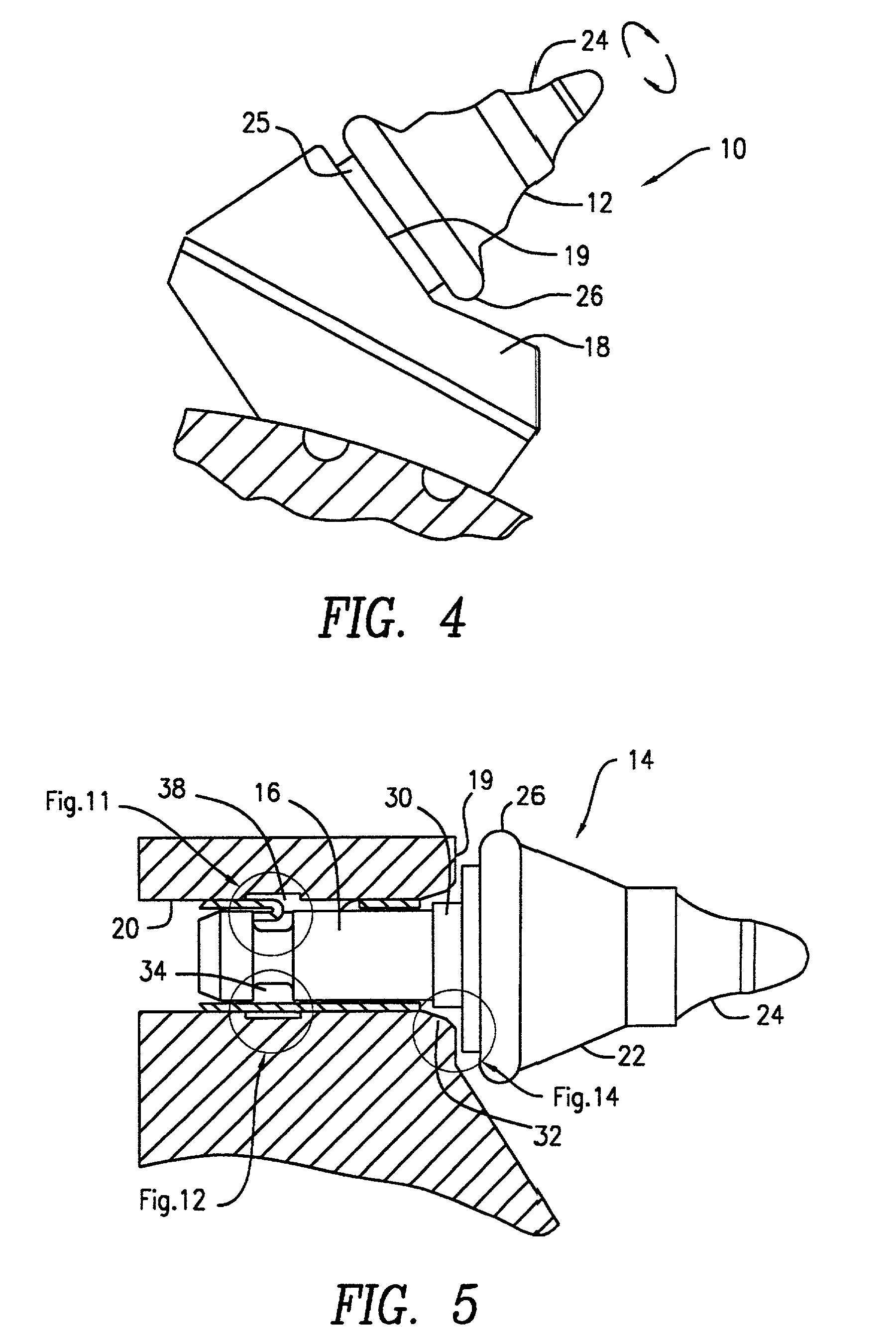
[0051]In a second alternative embodiment of the cutting tool assembly, the entire dimension shapes and geometries of the elements are identical to the embodiment illustrated in FIGS. 1-13 except for the distance between the shank neck surface and retainer endface. The relative position of the shank neck and retainer endface for the second alternative embodiment is illustrated in FIG. 14. In this second embodiment, the distance of the gap “B” between endface 45 and annular neck surface 29 is greater than the stroke distance “A” between the bendtop 41 of the stop tab and the inward facing surface 21. In this embodiment, when the cutting tool head is impacted against material during operation, the washer 25 abuts the front face 19 of the bit holder and inward facing edge surface 21 simultaneously contacts the bendtop 41. In the embodiment illustrated in FIG. 14, the axial play of the shank with respect to the retainer is determined by the cooperation of the shank groove with both the t...

first embodiment

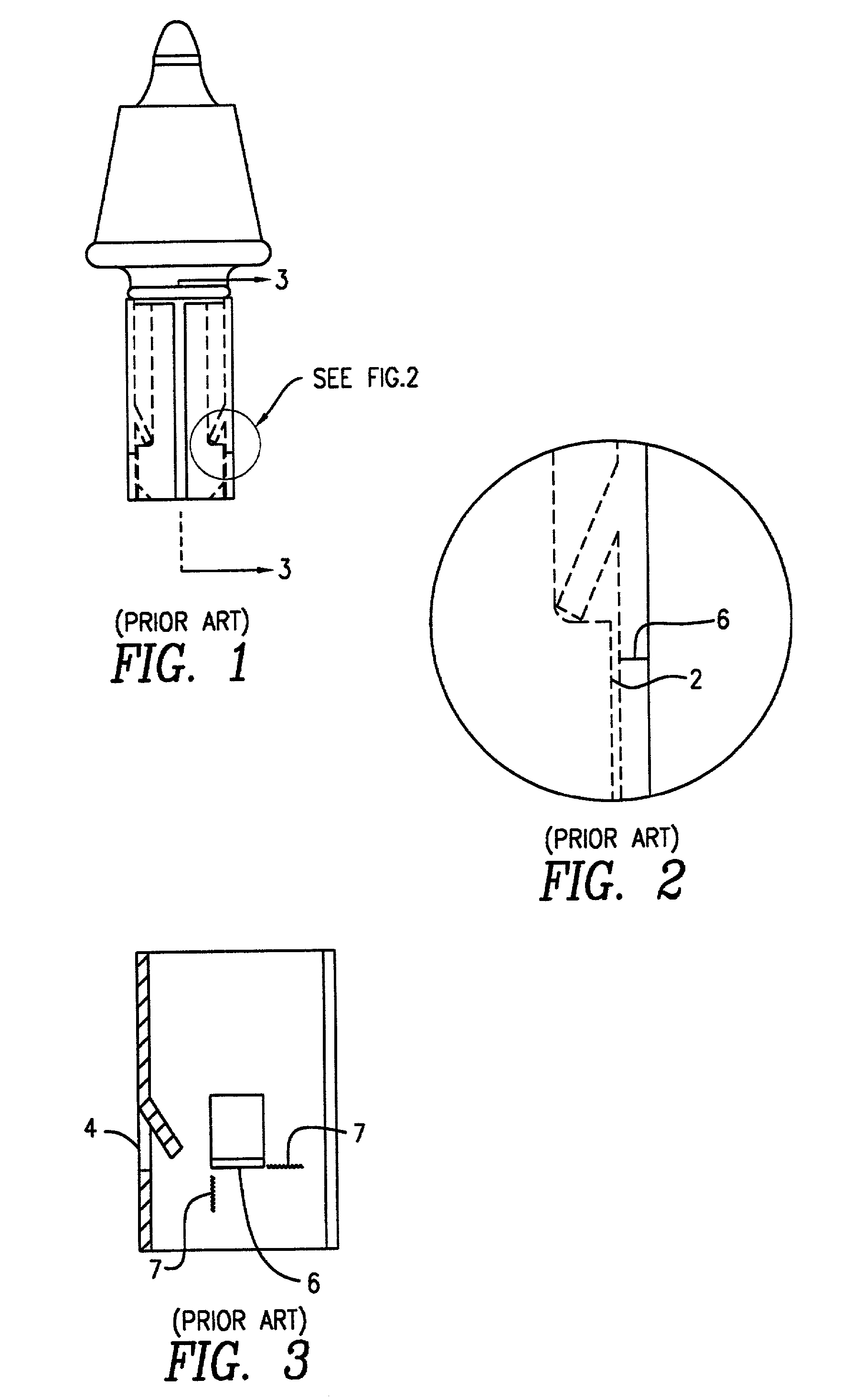
[0053]The present folded over stop tab spring retainer design can be alternatively designed without dimples as well-known in the prior art. The ability of the smooth retainer to secure the cutting bit within the bit holder is far less than the dimpled retainer embodiment illustrated in FIG. 5. Such an alternative embodiment of the subject invention is illustrated in FIG. 15, where like numerals are used to designate like elements among the figures. In this embodiment, the bit holder 18 includes a uniform cylindrical bore 20 (no notch) for receiving the cylindrical shank portion 16 of the cutting bit 12. As with the embodiment shown in FIG. 5, the shank portion 16 includes an annularly shaped groove 34. The bit holder 18 does not, however, include the annular notch or dimples as illustrated in FIG. 5. In this embodiment, the cutting tool assembly includes a retainer sleeve 40, which is disposed between the shank portion 16 of the cutting bit 12 and the bore 20 of the bit holder 18. T...


PUM


Abstract

A cutting tool assembly including a cutting bit having a head and a cylindrical shank portion of substantially constant diameter depending from the head as well as a bit holder including a cylindrical bore for receiving the cylindrical shank portion of the cutting bit. The shank portion includes an annular recessed groove. The cutting tool assembly further includes a retainer sleeve disposed between the shank portion of the cutting bit and the bore of the bit holder and which closely conforms about the shank portion while allowing the shank portion to rotate within the bore. The retainer sleeve includes at least one inwardly folded over stop tab that cooperates with the recessed groove to axially position the shank within the retainer. The retainer includes stop tabs that are bent around beyond the shear cut lines of the tab opening so that the hub portions of the shank do not transmit a force against these weakened shear cut areas of the retainer. The shank hub is positioned so that the hub rotates against only those portions of the retainer that are not weakened by shear line openings.

Description

BACKGROUND OF THE INVENTION[0001]1. Field of the Invention[0002]The present invention relates to rotatable cutting tool assemblies and more specifically to rotatable cutting tool assemblies having sleeve retainers for removable attachment of the cutting tool within a bored tool holder.[0003]2. Description of the Related Art[0004]The present invention is directed toward a cutting tool assembly employed in earth working, mining or construction applications wherein a cutting bit is held on a mounting block or bit holder that is affixed to a movable member. Such cutting tool assemblies have been employed for various excavating operations. These excavating operations can include removal of minerals as well as trenching, concrete cutting, road planing and other construction applications. The effective life expectancy of cutting tools is determined by the cutting tool's ability to be securely held in place and yet be free to rotate in order to promote uniform wear on the respective tip por...

Claims


Application Information

Patent Timeline
Patent Type & Authority Patents(United States)
IPC IPC(8): E21C35/18E21C35/197
CPCE21C35/197E21C2035/1826E21C35/188
Inventor OJANEN, RANDALL W.
Owner KENNAMETAL INC
Why Eureka
Try Eureka