Constant temperature crystal oscillator

a crystal oscillator and constant temperature technology, applied in the direction of oscillator stabilization, oscillator generator, electrical equipment, etc., can solve the problems of poor response characteristic to ambient temperature, more expensive than the substrate of glass epoxy material, etc., to achieve economic configuration, effectively utilize heat source, and effectively realize heat source

Inactive Publication Date: 2008-06-03
NIHON DEMPA KOGYO CO LTD
View PDF8 Cites 28 Cited by
  • Summary
  • Abstract
  • Description
  • Claims
  • Application Information

AI Technical Summary

Benefits of technology

[0017]The first object of the present invention is to improve the response characteristic to a temperature change, the second object of the present invention is to enhance the productivity by reducing the height, and the third object is to effectively use a heat source when a constant temperature oscillator is provided.

Problems solved by technology

Therefore, since the resistance value of the temperature sensitive resistor is not immediately changed in synchronization with the operation temperature of the surface-mount resonator, and the operation temperature cannot be detected in real time, there has been the problem that the response characteristic to an ambient temperature is poor.
Furthermore, since the second substrate 3b is made of a ceramic material, it is more expensive than a substrate of a glass epoxy material.

Method used


Image

  • Constant temperature crystal oscillator
  • Constant temperature crystal oscillator
  • Constant temperature crystal oscillator

Examples


first embodiment

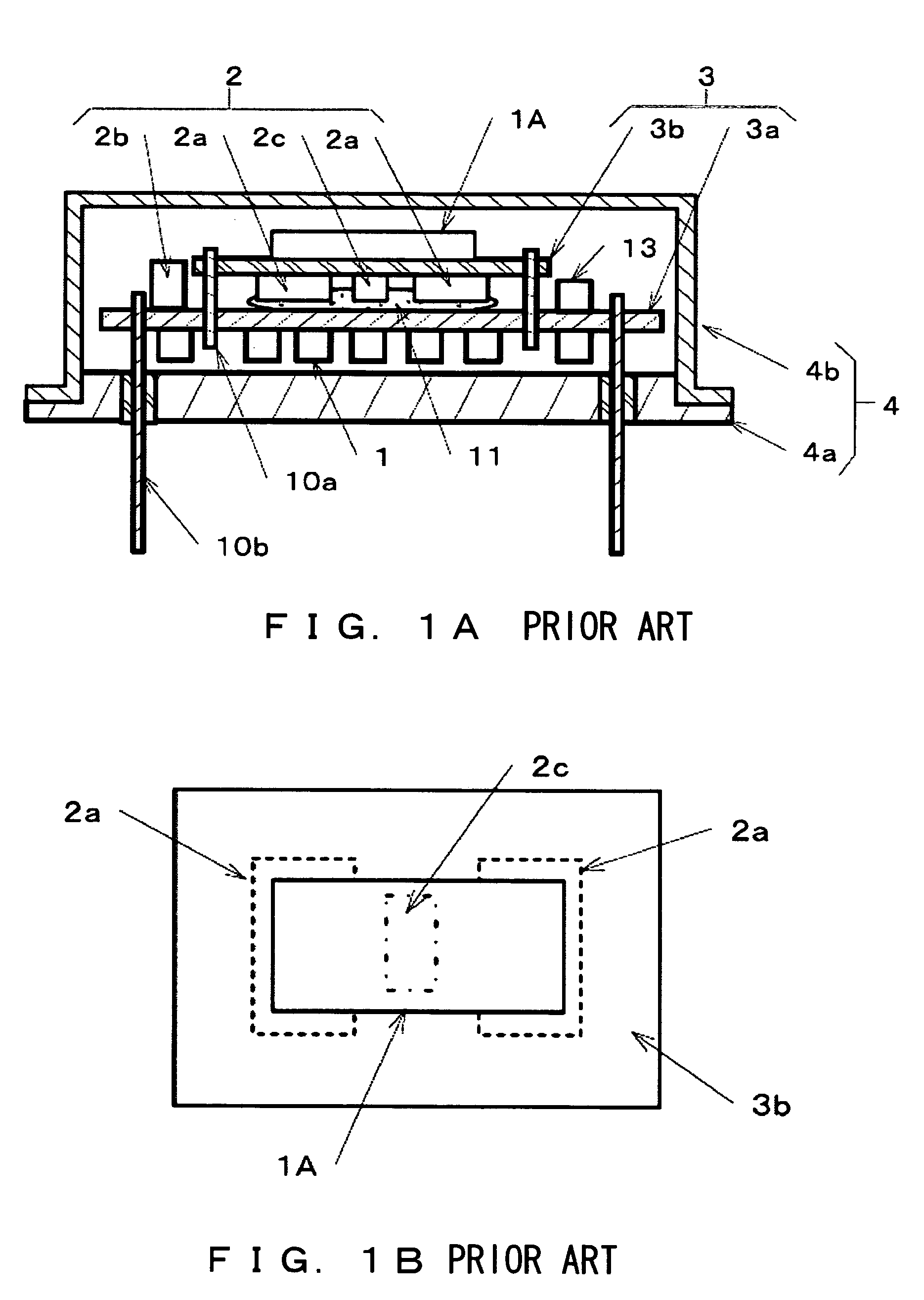
[0036]FIG. 4 is an explanatory view of the first embodiment of the present invention in which FIG. 4A is a sectional view of the constant temperature oscillator, and FIG. 4B is a plan view of the circuit substrate. The explanation of the same components of the related art is simply described or omitted here.

[0037]As described above, the constant temperature oscillator arranges on the circuit substrate 3 the existing surface-mount resonator 1A, the oscillation circuit element 1 forming an oscillation circuit with the resonator, and the temperature control element 2 for leveling the operation temperature by including at least the heating chip resistor 2a, the power transistor 2b, and the temperature sensitive resistor 2c. These components-are airtightly sealed in the metal container 4. In this example, the circuit substrate 3 is a single plate (single substrate) made of a glass epoxy material, and the bottom surface of the circuit substrate 3 faces the metal base 4a. The circuit subst...

second embodiment

[0048]FIGS. 5A and 5B are explanatory views of the second embodiment of the present invention, and are plan views of the circuit substrate of the constant temperature oscillator. The same components between the embodiment and the related art are assigned the same reference numerals, and the detailed explanation is simplified or omitted here.

[0049]According to the second embodiment shown in, for example, FIG. 5A, the substrate-side dummy terminal 14x connected to one of the dummy terminals 9b of the surface-mount resonator 1A extends at least to the central area facing the bottom surface of the surface-mount resonator 1A. For example, it also extends between the substrate-side crystal terminal 14 of a set of diagonal portions and the substrate-side dummy terminal 14x of the other set of diagonal portions. In FIG. 5B, one of the diagonal portion of the other set is commonly connected to the other substrate-side dummy terminal 14x. Thus, one of the substrate-side dummy terminal 14x bec...

third embodiment

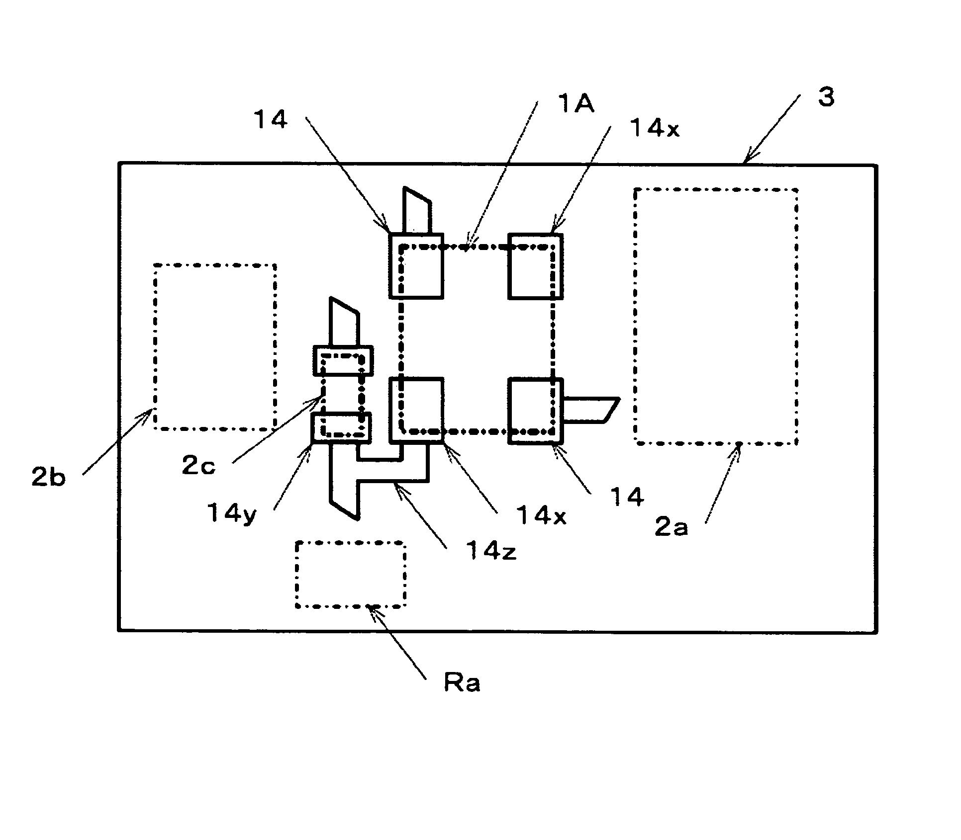
[0051]FIG. 6 is an explanatory view of the third embodiment of the present invention, and is a plan view of the circuit substrate of the constant temperature oscillator. The same components between the embodiment and the related art are assigned the same reference numerals, and the detailed explanation is simplified or omitted here.

[0052]In the third embodiment, the substrate-side dummy terminal 14x of the surface-mount resonator 1A is connected to the substrate-side resistor terminal 14y of the temperature sensitive resistor 2c as in the first embodiment through the conductive path 14z. In this example, the heating chip resistor 2a and the power transistor 2b arranged on both sides of the surface-mount resonator 1A are thermally connected. That is, the heating chip resistor 2a and the power transistor 2b are electrically connected (refer to FIG. 3A).

[0053]In this example, the substrate-side terminal 14 to which the chip resistor 2a and the power transistor 2b are fixed is connected...


PUM

PropertyMeasurementUnit
temperatureaaaaaaaaaa
constant temperatureaaaaaaaaaa

Abstract

A constant temperature crystal oscillator includes on a circuit substrate: a surface-mount crystal resonator which is provided with two crystal terminals as mount terminals and a dummy terminal on the bottom surface, and has a metal cover; an oscillation circuit element which forms an oscillation circuit together with the crystal resonator; and a temperature control element which keeps a constant operation temperature of the crystal resonator, in which the temperature control element includes at least a heating chip resistor, a power transistor for supplying electric power to the chip resistor, and a temperature sensitive resistor for detecting the operation temperature of the crystal resonator, wherein a dummy terminal on the substrate side of the circuit substrate for connection to the dummy terminal of the crystal resonator is connected to a resistor terminal on the substrate side to which the temperature sensitive resistor is connected through a conductive path.

Description

[0001]This application claims priority under 35 U.S.C. 119 to Japanese Application No. 2005-092067, filed Mar. 28, 2005 and Japanese Application No. 2006-023865, filed Jan. 31, 2006, which applications are incorporated herein by reference and made a part hereof.BACKGROUND OF THE INVENTION [0002]1. Field of the Invention[0003]The present invention relates to a constant temperature crystal oscillator (hereinafter referred to as a constant temperature oscillator) using a surface-mount crystal resonator (hereinafter referred to as a surface-mount resonator), and more specifically to a constant temperature oscillator which excels in response characteristic to a temperature change.[0004]2. Description of the Related Art[0005]Generally, a constant temperature oven has been used for a constant temperature oscillator. Since the operation temperature of a crystal resonator can be kept constant, the frequency stability is high (the frequency deviation is approximately 0.05 ppm or lower). For e...

Claims


Application Information

Patent Timeline
Patent Type & Authority Patents(United States)
IPC IPC(8): H03B5/32
CPCH03B5/04H03B5/36H03L1/028H03L1/04
Inventor ARAI, JUNICHISEKINE, NAOKI
Owner NIHON DEMPA KOGYO CO LTD
Why Eureka
Try Eureka