Display device conversion device, display device correction circuit, display device driving device, display device, display device examination device, and display method

a display device and conversion device technology, applied in the direction of color signal processing circuits, instruments, television systems, etc., can solve the problems of taking trouble and time to perform calculation, and taking many trouble to perform such processes, so as to achieve less trouble and time in approximation

Inactive Publication Date: 2008-06-03
SHARP KK
View PDF11 Cites 21 Cited by
  • Summary
  • Abstract
  • Description
  • Claims
  • Application Information

AI Technical Summary

Benefits of technology

[0016]The present invention was devised in view of the foregoing problems, and one of the features consistent with principles of embodiments of the present invention is to provide a display device conversion device, a display device correction circuit, a display device driving device, a display device, a display device examination device, and a display method, which require less trouble and time in approximating an input / output characteristic than a conventional technique.

Problems solved by technology

However, these arrangements recited in the foregoing publications raise the following problem: since an S-shaped curve indicative of an applied voltage-transmittance characteristic is approximated in accordance with plural functions, the continuity of the plural functions and positions at which the plural functions are connected to each other may be determined, so that it takes trouble and time to perform calculation (since the input voltage is divided into sections so as to approximate the applied voltage-transmittance of the liquid crystal by functions, the continuity of the divisional points may be considered and the points at which the characteristic should be divided may be determined, so that it takes trouble and time to perform calculation).
That is, in the case of dividing the characteristic into sections so as to approximate the characteristic by functions like the foregoing publications, it is necessary to consider the continuity of the divisional points and it is necessary to determine the positions at which the curve should be divided, and it takes much trouble to perform such processes.
Further, it is necessary to give a large number of parameters to the approximate expressions, so that it takes much time to perform such calculation.
Also, such condition raises the problem that the γ correction is inaccurately performed.

Method used


Image

  • Display device conversion device, display device correction circuit, display device driving device, display device, display device examination device, and display method
  • Display device conversion device, display device correction circuit, display device driving device, display device, display device examination device, and display method
  • Display device conversion device, display device correction circuit, display device driving device, display device, display device examination device, and display method

Examples


embodiment b 2

Embodiment b 2

[0134]The following description will explain another embodiment of the present invention with reference to FIG. 11.

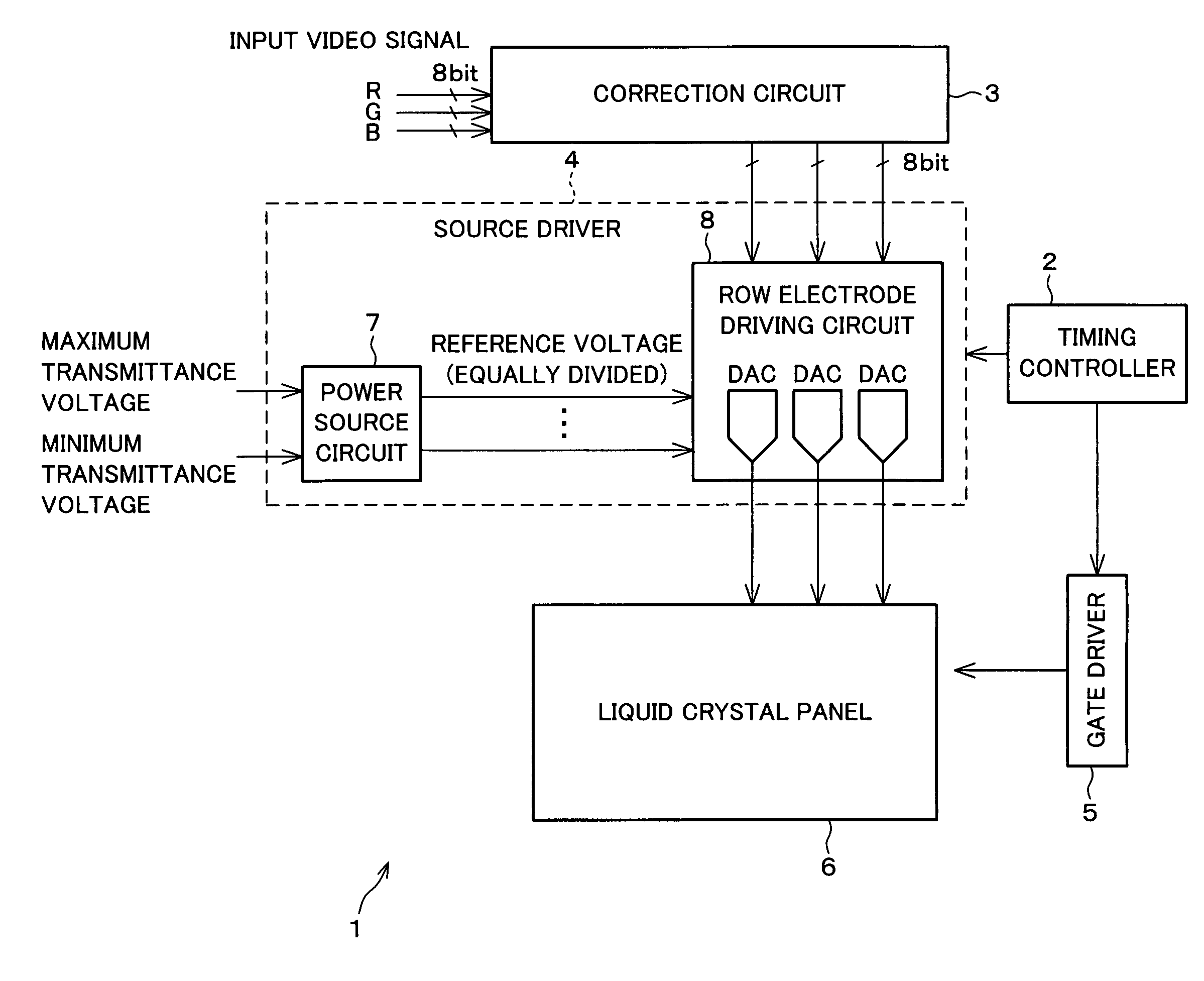
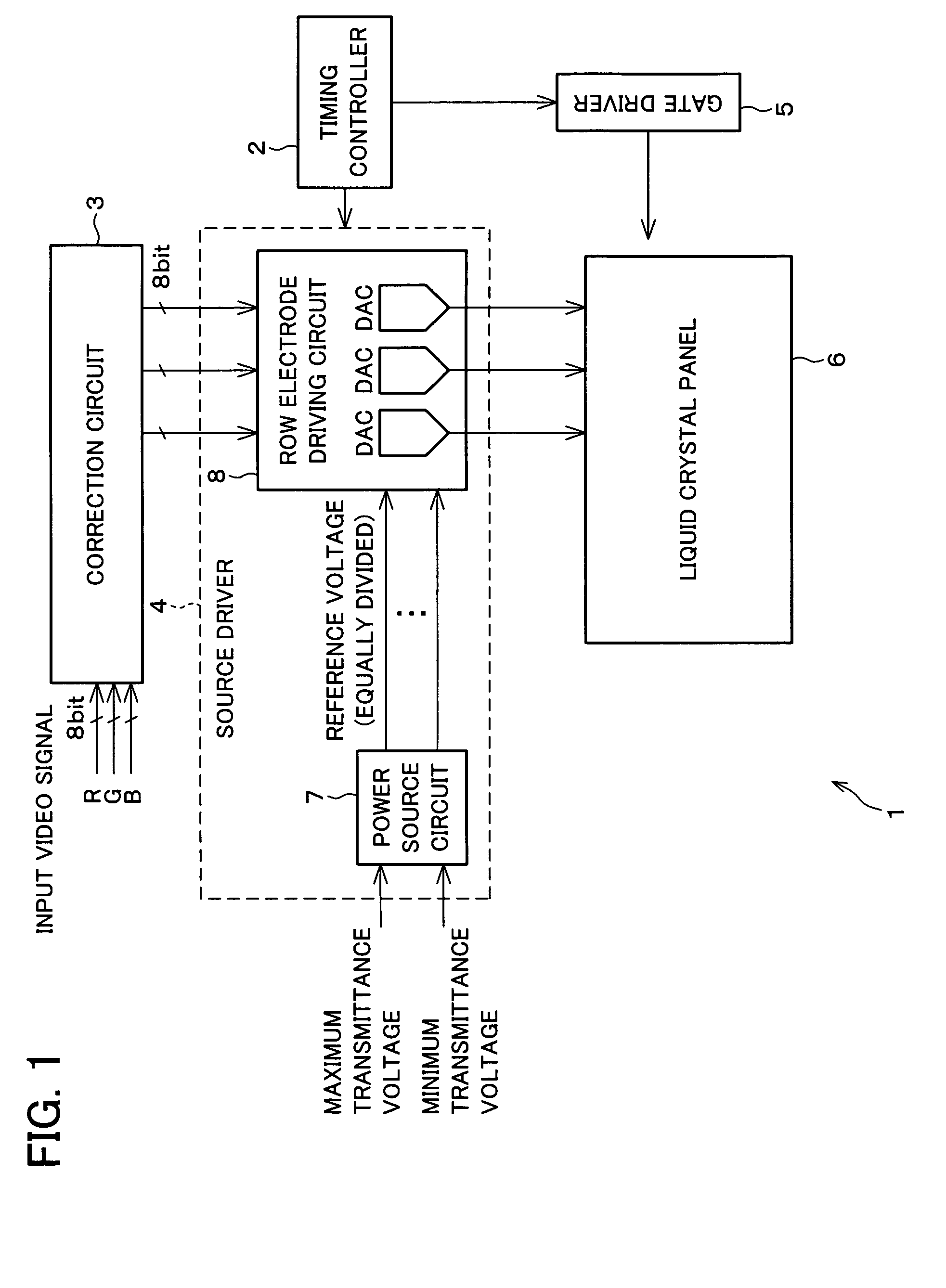
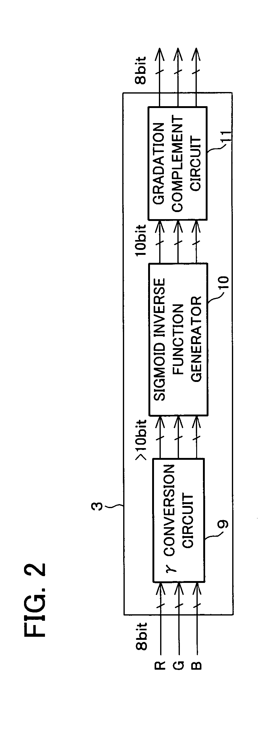
[0135]The examination device (display device examination device) 18 of the present embodiment, as shown in FIG. 11, examines the liquid crystal display device 1 described in Embodiment 1. Note that, FIG. 11 shows the correction circuit 3, the source driver 4, and the liquid crystal panel 6 and does not show the timing controller 2 and the gate driver 5 of the liquid crystal display device 1 shown in FIG. 1 so as to simplify the drawing. Further, illustration of the gradation interpolation circuit 11 of the correction circuit 3 is also omitted.

[0136]The examination device 18 includes a parameter calculating section 19, an examination pattern signal generator 20, and a luminance measuring device 21.

[0137]The parameter calculating section 19 calculates a parameter of the sigmoid function used to approximate the characteristic (V-T curve) of the liquid crystal...


PUM

PropertyMeasurementUnit
γaaaaaaaaaa
luminanceaaaaaaaaaa
voltage-transmittanceaaaaaaaaaa

Abstract

The liquid crystal display device inputs a signal, corrected by a correction circuit provided with a sigmoid inverse function generator, to a source driver. A sigmoid function which is an S-shaped function is used to approximate an input/output characteristic (applied voltage-transmittance curve) of a liquid crystal panel. The sigmoid inverse function generator converts an input signal by using an inverse function of the sigmoid function obtained by performing the approximation. A γ conversion circuit provided on the correction circuit and the sigmoid inverse function generator realize the desired γ characteristic regardless of a characteristic of the liquid crystal panel. Further, since the inverse function of the sigmoid function which is an S-shaped function is used, it is possible to provide a display device which corrects the input/output characteristic of the display panel by performing the approximation in accordance with not plural functions but a single function (without dividing the characteristic into sections).

Description

[0001]This Nonprovisional application claims priority under 35 U.S.C. § 119(a) on Patent Application No. 2002 / 381486 filed in Japan on Dec. 27, 2002, the entire contents of which are hereby incorporated by reference.FIELD OF THE INVENTION[0002]The present invention relates to a display device conversion device, a display device correction circuit, a display device driving device, a display device, a display device examination device, and a display method, by which an inputted video signal is converted. More specifically, the present invention relates to a display device conversion device, a display device correction circuit, a display device driving device, a display device, a display device examination device, and a display method, by which, for example, (i) correction is performed in accordance with an applied voltage-transmittance characteristic of liquid crystal, and (ii) γ correction is performed so as to adjust a γ characteristic indicative of a relationship between an imaging...

Claims


Application Information

Patent Timeline
Patent Type & Authority Patents(United States)
IPC IPC(8): G09G5/10G09G3/36G02F1/133G09G3/20H04N9/69
CPCG09G3/3688H04N9/69H04N9/315G09G3/2051G09G2320/0285G09G2320/0276G09G3/36
Inventor FURUKAWA, HIROYUKIYOSHIDA, YASUHIROUENO, MASAFUMI
Owner SHARP KK
Why Eureka
Try Eureka