Bolt fastening method and apparatus

Inactive Publication Date: 2009-04-02
MAZDA MOTOR CORP
View PDF7 Cites 1 Cited by
  • Summary
  • Abstract
  • Description
  • Claims
  • Application Information

AI Technical Summary

Benefits of technology

[0004]The present invention has been devised in view of the above-described matters, and an object of the present invention is to provide a bolt fastening method which can properly restrain the variation in the fastening shaft

Problems solved by technology

In the above-described bolt fastening method (torque+angle method), however, there may occur the variation in the fastening shaft force according to the coefficient of friction (between the screw face and the seat face) in the fastening area before reaching the snug torque Ts, which may improperly affect the fastening shaft force F of the fastening after the fastening point of the snug torque Ts (see FIG. 12).
In this case, while it may be con

Method used


Image

  • Bolt fastening method and apparatus
  • Bolt fastening method and apparatus
  • Bolt fastening method and apparatus

Examples


Example

[0032]77A bolt fastening method according to a first embodiment will be described

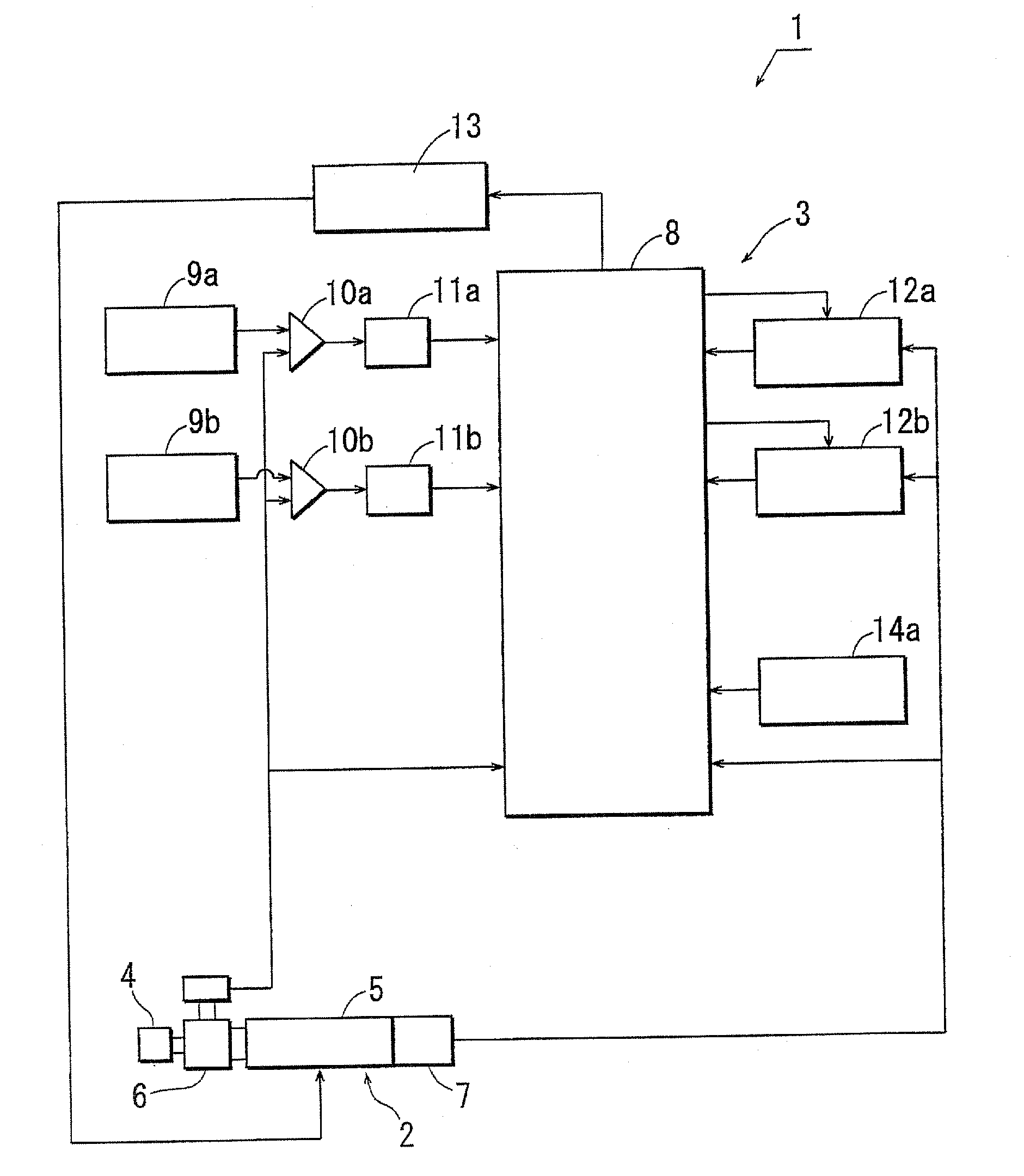
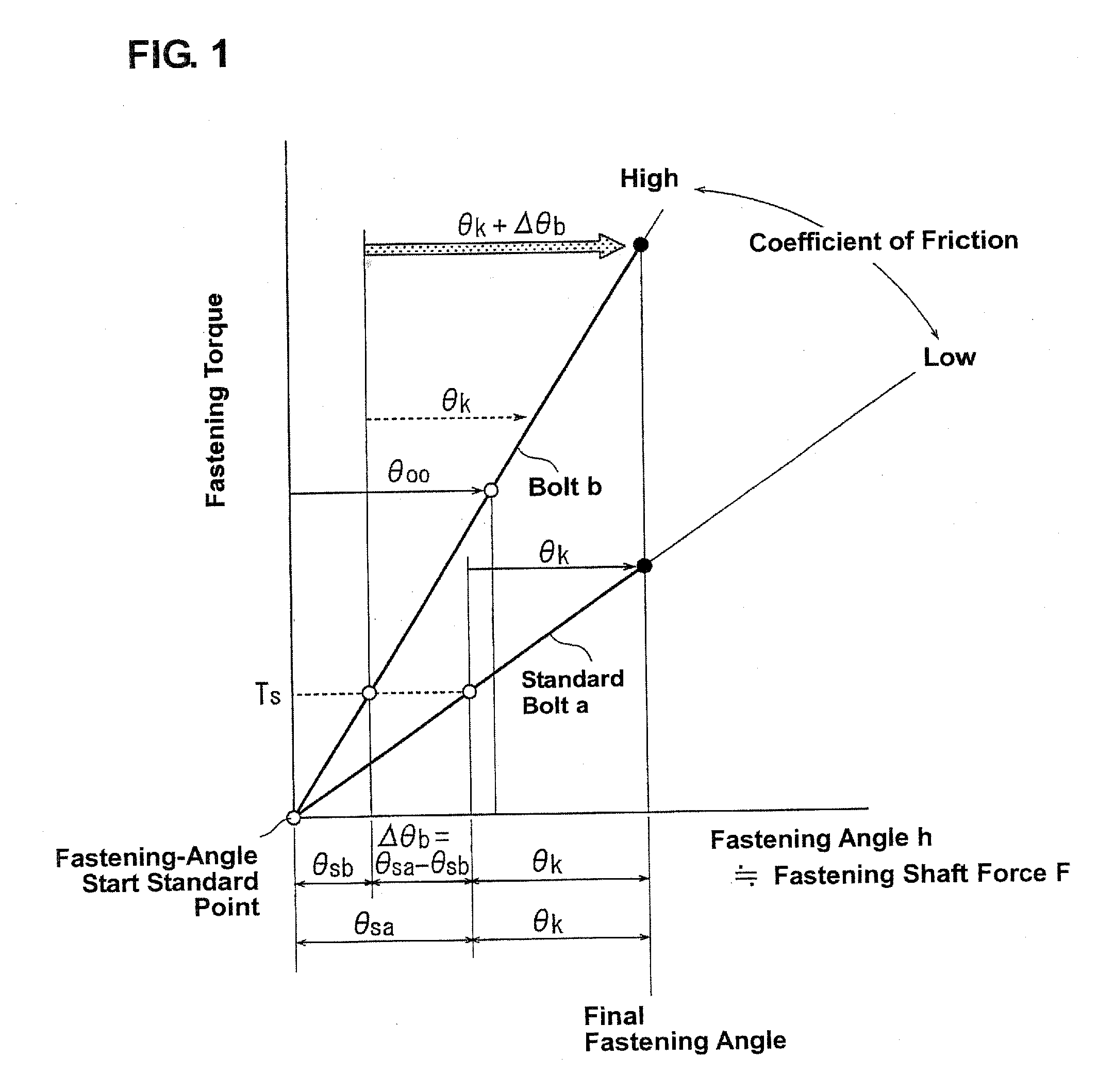
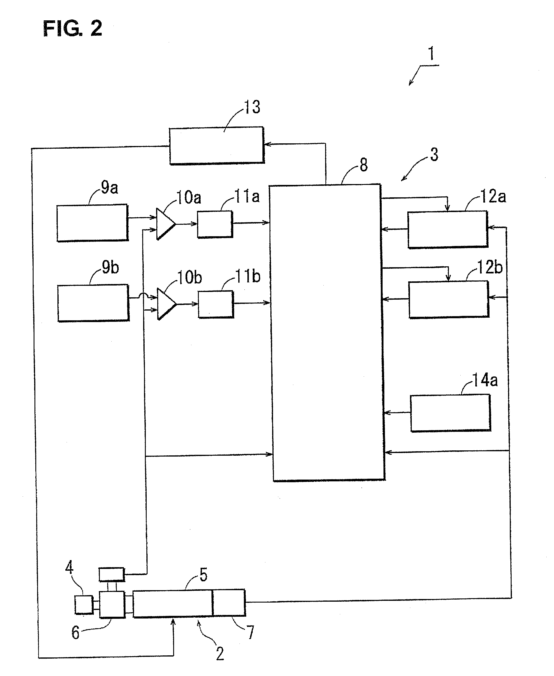
[0033][1] In a bolt fastening method according to the first embodiment, the bolt is fastened to a fastened member (engine bearing parts, for example) with a bolt rotating device such as a nut runner, and a fastened member is fastened with the bolt. Herein, the bolt is fastened up to a predetermined snug torque Ts and then the bolt is further fastened by a specified angle from a bolt angle corresponding to the snug torque Ts (torque+angle method). If the torque method (the method of managing bolt fastening with the fastening torque which utilizes the proportional relationship between the fastening torque and the fastening shaft force (in the elasticity area of bolt)), which is shown in FIG. 11, was applied, the fastening shaft force of the bolt would varies improperly according to the coefficient of friction between the screw face and the seat face of the bolt. The torque+angle method, however, uses addi...

Example

[0063]Hereinafter, a bolt fastening method according to a second embodiment will be described. Herein, like the above-described first embodiment, the torque+angle method is applied in which the difference Δθ, and the addition of this difference Δθb to the base angle θk is set as the new specified angle. According to the bolt fastening method according to the second embodiment, however, the fastening angles of a plurality of bolts to be fastened at the point where the fastening torque of each bolt has reached the snug torque Ts are detected, an average angle θave of the obtained fastening angles of the plurality of bolts is obtained, and the average angle θave is used as the standard angle. Thereby, the correction of the fastening shaft force of the bolts can be properly achieved regardless of presence of the plural bolts to be fastened, so that the fastening shaft forces of the plural bolts can be made uniform. In this case, part of all of the bolts which are to be fastened can be s...


PUM

PropertyMeasurementUnit
Angleaaaaaaaaaa
Torqueaaaaaaaaaa

Abstract

A bolt is fastened up to a predetermined snug torque Ts and then the bolt is further fastened by a specified angle θt from a bolt angle corresponding to the snug torque Ts. Herein, in order to obtain excess and deficiency of the fastening angle up to the snug torque Ts, an angle-variation difference between the fastening angle θsb of the bolt at the point where the fastening torque of the bolt has reached the snug torque Ts and a standard angle θsa of the snug torque Ts is calculated. And, addition of this angle-variation difference to a base angle is set as the new specified angle θt to correct the excess and deficiency. Accordingly, variation in a fastening shaft force can be restrained even if the snug torque is set at a relatively high torque in the bolt fastening method using the torque+angle method.

Description

BACKGROUND OF THE INVENTION[0001]The present invention relates to a bolt fastening method and apparatus.[0002]A bolt fastening method (torque method) in which the bolt fastening management is conducted by utilizing the proportional relationship between the fastening torque T and the fastening shaft force (in the bolt elasticity area) is known. While this torque method is superior in work efficiency, there may occur a large variation in the fastening shaft force according to the coefficient of friction between the screw face and the seat face of the bolt (see FIG. 11). Accordingly, another bolt fastening method (torque+angle method), which is shown in US Patent Application Publication No. 2006 / 0218768, has been used, in which the bolt is fastened up to the predetermined snug torque Ts (a fastening torque at a start point for an effective and substantial fastening) and then the bolt is further rotated (fastened) by a specified angle θk from the standard bolt angle corresponding to the...

Claims


Application Information

Patent Timeline
IPC IPC(8): B25B23/14
CPCB23P19/066Y10T29/49767Y10T29/49766B25B23/14
Inventor MAKIMAE, TATSUMIFUJII, YUTAKA
Owner MAZDA MOTOR CORP
Why Eureka
Try Eureka