Method for controlling convection pattern of silicon melt, method for producing silicon single crystals, and device for pulling silicon single crystals

Pending Publication Date: 2020-12-24
SUMCO CORP
View PDF5 Cites 0 Cited by
  • Summary
  • Abstract
  • Description
  • Claims
  • Application Information

AI Technical Summary

Benefits of technology

The invention relates to a pull-up device for producing high-quality silicon wafers. By using a heating portion with differential heating capacity on either side of a pull-up device, the device can better control the temperature of the silicon melt and prevent variations in oxygen concentration between the resulting wafers. Additionally, a horizontal magnetic field can be applied to facilitate convection flow and restrain variations in the diameter of the silicon in the pull-up direction. Overall, this invention provides a simple and effective method for producing high-quality silicon wafers.

Problems solved by technology

However, no definitive solution has been found.
Although the direction of the convection flow 90 is fixedly determined clockwise or anticlockwise depending on the state of the convection flow immediately before the horizontal magnetic field is applied, since a position of the downward flow move at random, it is difficult to control the state of the convection flow immediately before the horizontal magnetic field is applied.

Method used


Image

  • Method for controlling convection pattern of silicon melt, method for producing silicon single crystals, and device for pulling silicon single crystals
  • Method for controlling convection pattern of silicon melt, method for producing silicon single crystals, and device for pulling silicon single crystals
  • Method for controlling convection pattern of silicon melt, method for producing silicon single crystals, and device for pulling silicon single crystals

Examples


first exemplary embodiment

[1] First Exemplary Embodiment

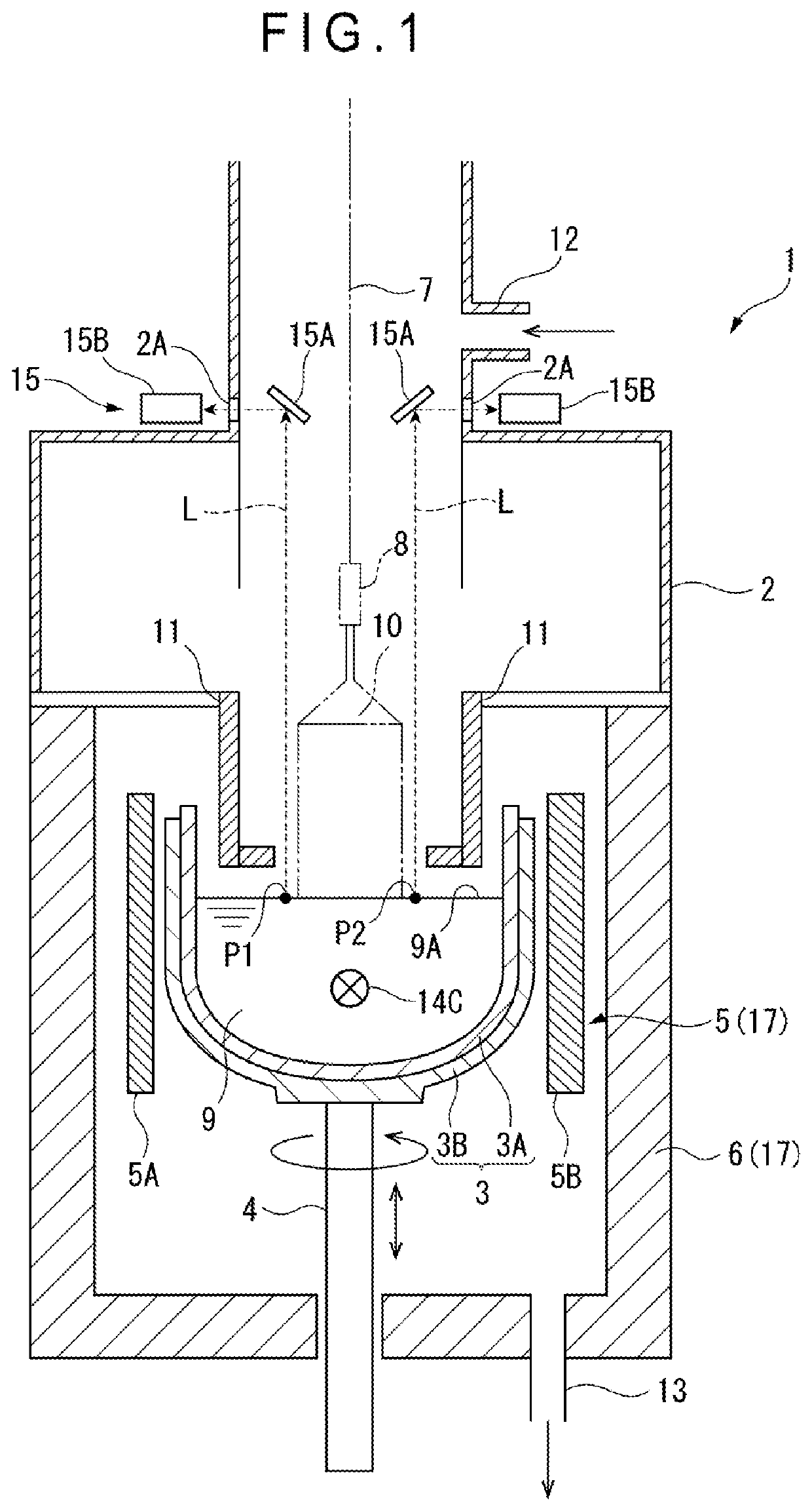
[0041]FIG. 1 schematically illustrates an exemplary structure of a pull-up device 1 of monocrystalline silicon to which a manufacturing method of monocrystalline silicon 10 according to a first exemplary embodiment of the invention is applicable. The pull-up device 1, which is a device for pulling up the monocrystalline silicon 10 through the Czochralski method, includes a chamber 2 forming an outer shell and a crucible 3 disposed at the center of the chamber 2.

[0042]The crucible 3, which has a double structure of an inner quartz crucible 3A and an outer graphite crucible 3B, is fixed to an upper end of a support shaft 4 that is rotatable and movable up and down.

[0043]A resistance heating type heater 5 is provided outside the crucible 3 in a manner to surround the crucible 3. A heat insulation material 6 is provided outside the heater 5 and along an inner surface of the chamber 2. The heater 5, the heat insulation material 6, and a voltage-applying port...

second exemplary embodiment

[5] Second Exemplary Embodiment

[0096]Next, a second exemplary embodiment of the invention will be described. In the following description, the same reference numerals will be given to the components already described and the description thereof will be omitted.

[0097]The second exemplary embodiment is different from the first exemplary embodiment in a structure of a heating portion 31 and a structure of a controller 40.

[0098]The heating portion 17 includes a heater 30, the heat insulation material 6 as shown in FIGS. 8A, 8B, and a voltage-applying portion 16A (see FIG. 4).

[0099]The heater 30 includes a first section heater 30A on the left and a second section heater 30B on the right with respect to the imaginary line 9C. The first and second section heaters 30A, 30B are separate bodies shaped in the same-sized semi-cylinder in a plan view. Moreover, the first and second section heaters 30A, 30B are the same in terms of the resistance value.

[0100]The voltage-applying portion 16A appli...

third exemplary embodiment

[8] Third Exemplary Embodiment

[0111]Next, a third exemplary embodiment of the invention will be described. In the following description, the same reference numerals will be given to the components already described and the description thereof will be omitted.

[0112]The third exemplary embodiment is different from the first exemplary embodiment in a structure of a heating portion 52.

[0113]The heating portion 52 includes a heater 50, a heat insulation material 51 as shown in FIGS. 9A, 9B, and the voltage-applying portion 16 (see FIG. 4).

[0114]The heater 50 is formed cylindrical in a plan view. A resistance value of the heater 50 is constant all over a circumference thereof. Accordingly a heat generation amount of the heater 50 is constant all over the circumference thereof.

[0115]The heat insulation material 51 includes a first divided heat insulation material 51A on the left and a second divided heat insulation material 51B on the right with respect to the imaginary line 9C. The first ...


PUM


Abstract

A convection pattern control method includes: heating a silicon melt in a quartz crucible using a heating portion; and applying a horizontal magnetic field to the silicon melt in the quartz crucible being rotated. In the heating of the silicon, the silicon melt is heated with the heating portion whose heating capacity differs on both sides across an imaginary line passing through a center axis of the quartz crucible and being in parallel to a central magnetic field line of the horizontal magnetic field when the quartz crucible is viewed from vertically above. In the applying of the horizontal magnetic field, the horizontal magnetic field of 0.2 tesla or more is applied to fix a direction of a convection flow in a single direction in a plane orthogonal to an application direction of the horizontal magnetic field in the silicon melt.

Description

TECHNICAL FIELD[0001]The present invention relates to a convection pattern control method of a silicon melt, a manufacturing method of monocrystalline silicon, and a pull-up device of monocrystalline silicon.BACKGROUND ART[0002]A method called Czochralski method (hereinafter, referred to as CZ method) is used for manufacturing monocrystalline silicon. In such a manufacturing method using the CZ method, various studies have been made for improving a quality of monocrystalline silicon (see, for instance, Patent Literatures 1 and 2).[0003]Patent Literature 1 discloses that point defects can be reduced by pulling up monocrystalline silicon while controlling a temperature of a silicon melt to be uniform in a radius direction of the monocrystalline silicon.[0004]Patent Literature 2 discloses that a fluctuation in an impurity concentration or a dopant concentration of monocrystalline silicon in a radius direction can be reduced by misaligning a rotation axis of the monocrystalline silicon ...

Claims


Application Information

Patent Timeline
IPC IPC(8): C30B29/06C30B15/20C30B30/04
CPCC30B30/04C30B29/06C30B15/206C30B15/305C30B15/20C30B15/14C30B29/14
Inventor SAKAMOTO, HIDEKISUGIMURA, WATARUYOKOYAMA, RYUSUKEMATSUSHIMA, NAOKI
Owner SUMCO CORP
Why Eureka
Try Eureka