
Manufacturing method for fuel cell

Pending Publication Date: 2021-12-02
TOYOTA JIDOSHA KK
View PDF1 Cites 0 Cited by
  • Summary
  • Abstract
  • Description
  • Claims
  • Application Information

AI Technical Summary

Benefits of technology

The patent proposes a method for manufacturing a separator used in fuel cells. By applying a laser beam to the surface of a metal plate, the surface of the separator can be reformed. However, the traditional method resulted in unstable shapes of the separator after laser application, due to the lack of control over the warping amount. This could lead to defects in the manufacturing process. The new method proposes a way to restrain variation in the warping amount of the separator, resulting in a stable shape of the metal plate after laser application. This ensures a reliable and consistent manufacturing process for fuel cells.

Problems solved by technology

In the related art, it is difficult to control the warping amount of the separator to be warped due to application of the laser beam, and the warping amount largely varies.
Because of this, defects might occur when a fuel cell is manufactured by use of the separator.
As a result, large warps are caused in the four high-energy regions in the metal plate.

Method used


Image

  • Manufacturing method for fuel cell
  • Manufacturing method for fuel cell
  • Manufacturing method for fuel cell

Examples


embodiment 1

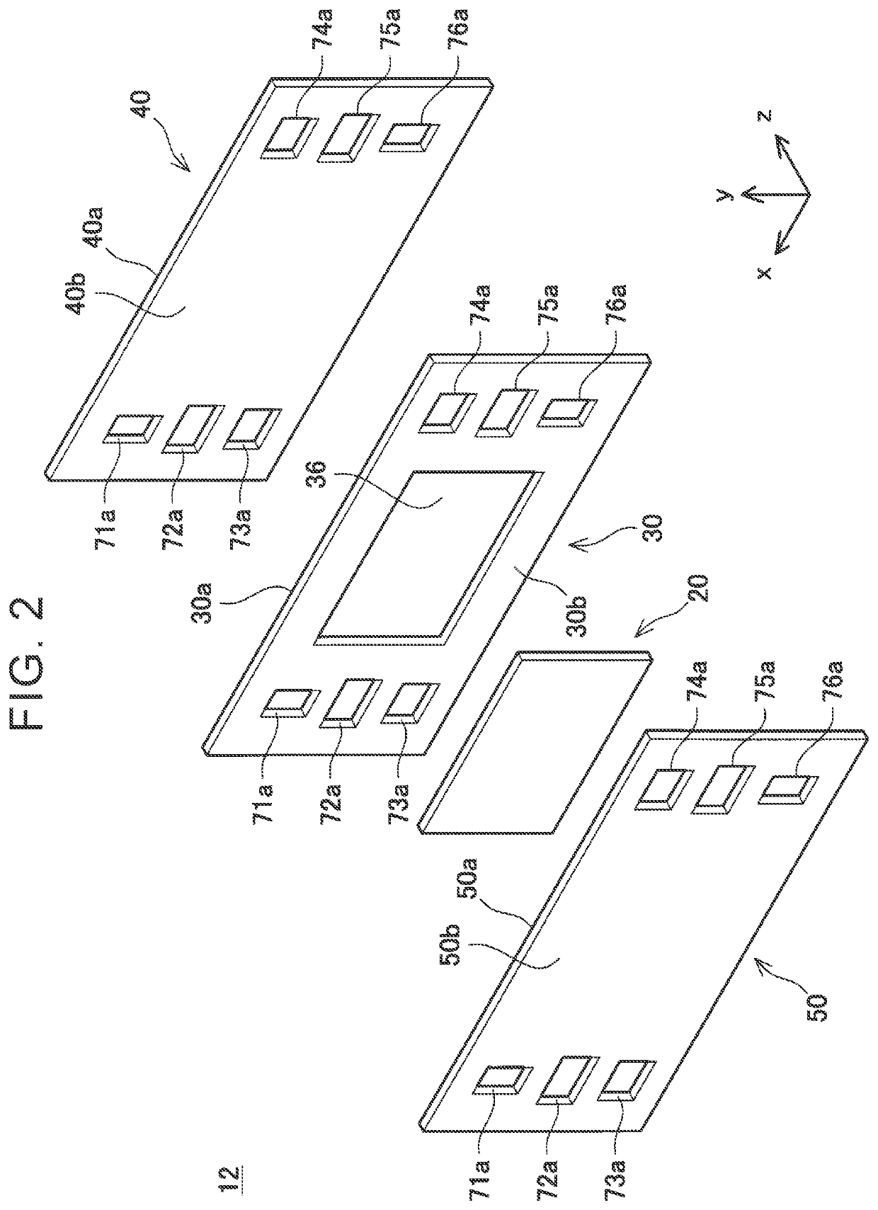
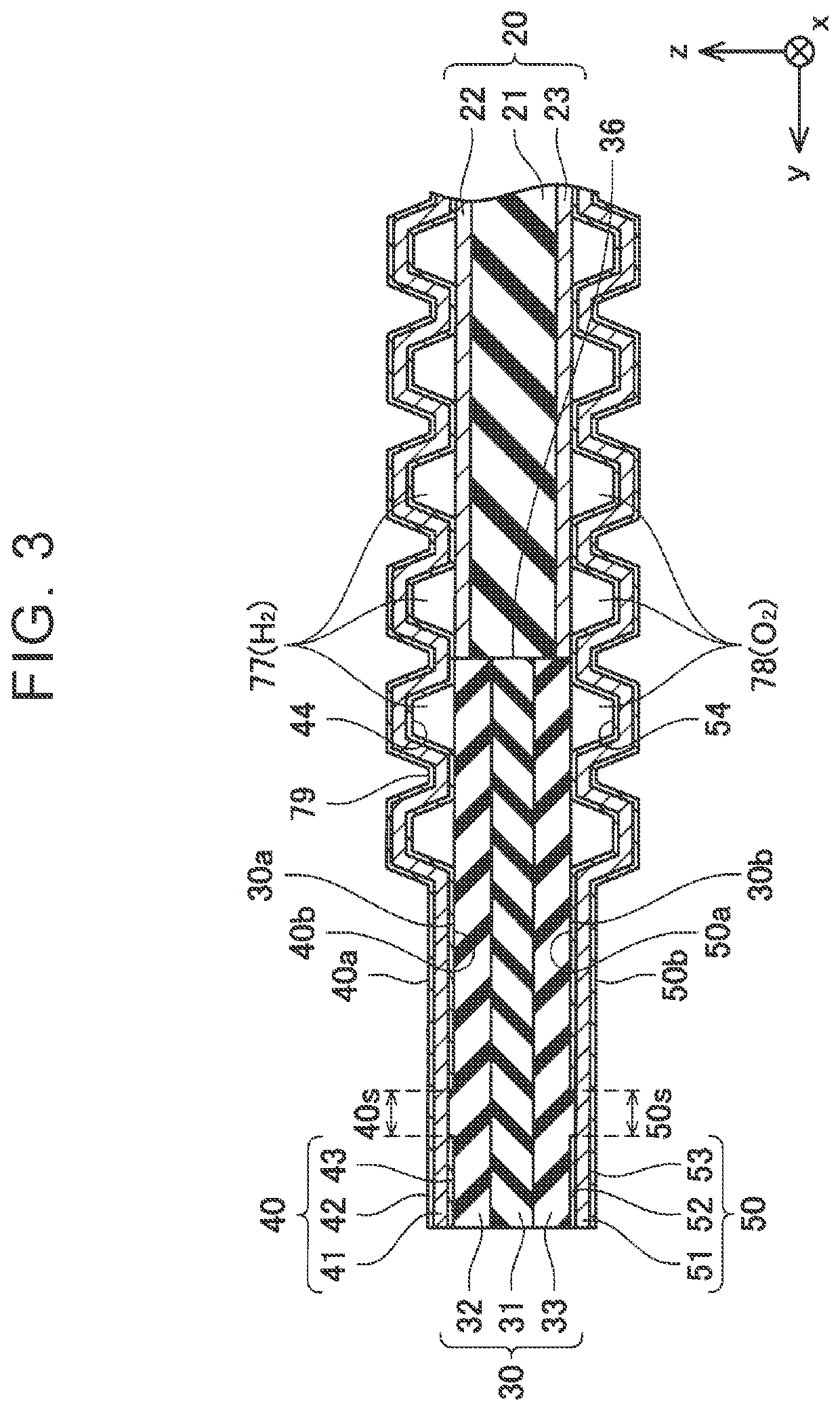
[0053]Next will be described a manufacturing method for manufacturing the separator 40 of Embodiment 1. First, the through-holes 71a to 76a and the grooves 44 are formed in the metal plate 41 by press working or the like.

[0054]Coating Step

[0055]Then, as illustrated in FIG. 6, the carbon films 42, 43 are formed to cover the whole surface of the metal plate 41. Herein, the carbon films 42, 43 are formed with a thickness of 10 nm to 100 nm.

[0056]Laser Application Step

[0057]Then, as illustrated in FIG. 7, a laser beam L (for example, a YAG laser beam) is applied to part of the surface 40b (that is, a surface of the carbon film 43) of the separator 40. Since the carbon film 43 easily absorbs a laser beam, the separator 40 is heated to a high temperature within an application range of the laser beam. Because of this, the carbon film 43 is removed by evaporation. Hereby, the ranges 40s in which the carbon film 43 is removed are formed. Herein, the ranges 40s are formed as illustrated in FI...

embodiment 4

[0071]Note that, in Embodiment 4, the warp correction step is performed only on the separator 40 with a large warping amount. However, the warp correction step may be performed on all the separators 40 to be manufactured. With this configuration, it is possible to reduce the warping amounts of the separators 40.

[0072]Note that, in Embodiments 1 to 4, the surfaces of the metal plates 41, 51 are covered with a carbon film, but the surfaces of the metal plates 41, 51 may not be covered with a carbon film. That is, the metal plates 41, 51 may be exposed over the whole surfaces of the separators 40, 50. In a manufacturing process of the separators 40, 50 configured as such, a laser beam may be applied to the metal plates 41, 51 for the purpose of removing dirt on the surfaces of the metal plates 41, 51. In this case, with the use of the technologies of Embodiments 1 to 4, it is possible to restrain variation in the warping amounts of the separators 40, 50. Further, in this case, the surf...


PUM

PropertyMeasurementUnit
Lengthaaaaaaaaaa
Widthaaaaaaaaaa
Energyaaaaaaaaaa

Abstract

A manufacturing method for manufacturing a separator for a fuel cell includes a step of applying a laser beam to a surface of a plate-shaped metal plate having a rectangular shape such that an application range of the laser beam extends linearly. In the step, the laser beam is applied such that the application range includes a high-energy region in which energy to be given by the laser beam per unit distance in a direction where the application range extends linearly is high, and a low-energy region in which the energy is low. The high-energy region includes a first region, a second region, a third region, and a fourth region. The first region and the second region extend in parallel to one of long sides of the rectangular shape. The third region and the fourth region extend in parallel to the other one of the long sides.

Description

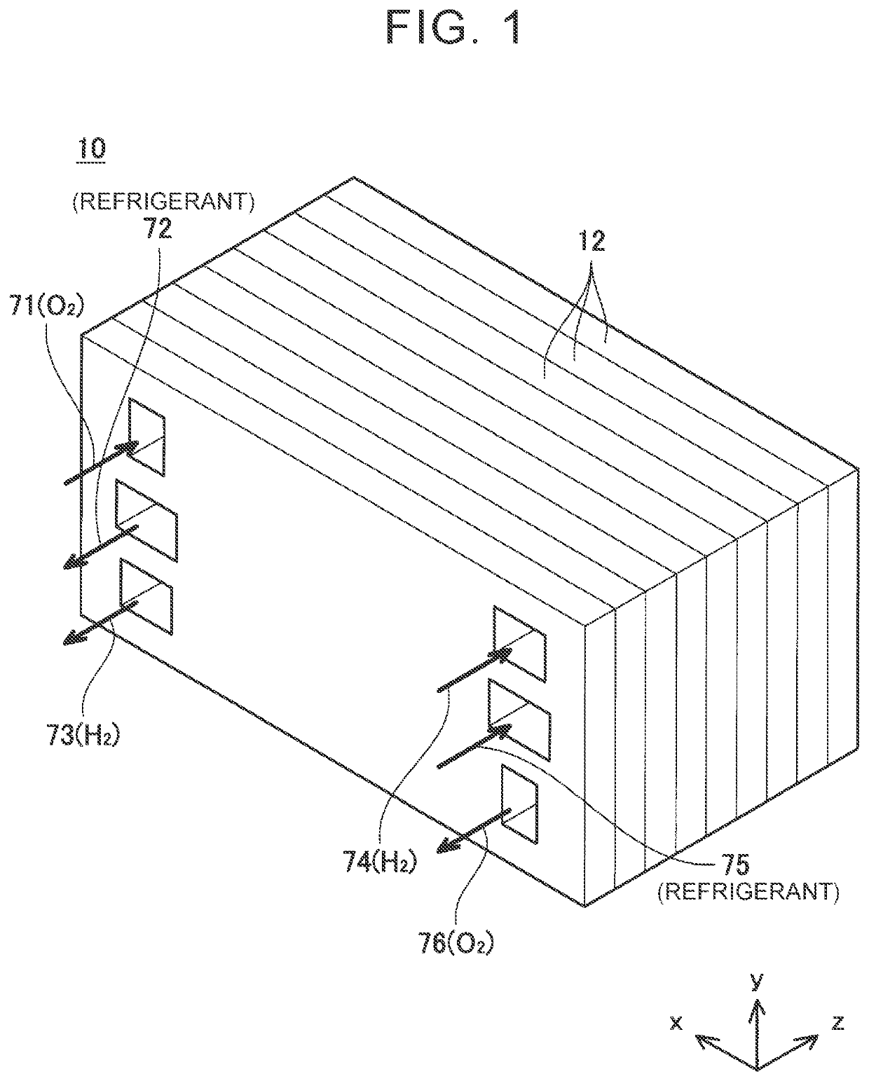
CROSS-REFERENCE TO RELATED APPLICATION[0001]This application claims priority to Japanese Patent Application No. 2020-091599 filed on May 26, 2020, incorporated herein by reference in its entirety.BACKGROUND1. Technical Field[0002]The technology described in the present specification relates to a manufacturing method for a fuel cell.2. Description of Related Art[0003]A fuel cell described in Japanese Unexamined Patent Application Publication No. 2015-173108 (JP 2015-173108 A) includes a separator constituted by a metal plate. The fuel cell is configured such that the separator is bonded to a frame in which an electrode member is accommodated.SUMMARY[0004]When a laser beam is applied to a separator, a surface of the separator may be reformed. For example, when the laser beam is applied to the separator, dirt on the surface of the separator may be removed. When the laser beam is applied to the separator as such, an outer layer part of the separator melts and then solidifies. The outer ...

Claims


Application Information

Patent Timeline
IPC IPC(8): H01M8/0206B23K26/20H01M8/0267
CPCH01M8/0206H01M8/0267B23K26/20B08B7/0042H01M8/0202H01M2008/1095Y02E60/50Y02P70/50
Inventor SAKANOI, RYOTAKOBAYASHI, HIROOMIWATANABE, YUTAHANAKURA, YOICHI
Owner TOYOTA JIDOSHA KK
Learn More