Material for plastic lens, production process of the material, composition for plastic lens, plastic lens obtained by curing the composition, and production process of the plastic lens

a technology of plastic lens and composition, which is applied in the direction of optics, instruments, optical elements, etc., can solve the problems of low resistance to solvent or scratching, insufficiently high value of plastic lens with respect to birefringence and light scattering, and high refractive index

Inactive Publication Date: 2003-07-17
SHOWA DENKO KK
View PDF0 Cites 1 Cited by
  • Summary
  • Abstract
  • Description
  • Claims
  • Application Information

AI Technical Summary

Benefits of technology

0098] The plastic lens composition of the present invention (III) or the present invention (IV) has an alicyclic structure, accordingly, depending on the molecular design, the refractive index can be easily approximated to the refractive index 1.498 of the plastic lens starting from polydiethylene glycol bis(allyl carbonate) which is used for plastic lenses in many cases. This is advantageous in that the mold or the like conventionally used in the molding need not be changed but can be used as it is.

Problems solved by technology

The plastic lens derived from polystyrene resin has a problem in that a sufficiently high value cannot be obtained with respect to birefringence and light scattering, though the refractive index is high.
The plastic lens derived from polycarbonate resin is disadvantageously inferior in resistance against a solvent or scratching, though the impact resistance is high.
In the plastic lens derived from polymethyl methacrylate resin, the refractive index is low and the impact resistance is not at a satisfactory level.
If the curing shrinkage in percentage is excessively large, cracks may be generated on the lens when the curing speed is increased, or the lens or the mold may be damaged at the release of lens from the mold.

Method used


Image

  • Material for plastic lens, production process of the material, composition for plastic lens, plastic lens obtained by curing the composition, and production process of the plastic lens
  • Material for plastic lens, production process of the material, composition for plastic lens, plastic lens obtained by curing the composition, and production process of the plastic lens
  • Material for plastic lens, production process of the material, composition for plastic lens, plastic lens obtained by curing the composition, and production process of the plastic lens

Examples


production example 1

[0118] Into a 500 ml three-neck flask with a distillation unit, 160.2 g of dimethyl glutarate, 232.3 g of allyl alcohol, 0.27 g of potassium acetate and 1.33 g (1% by mass based on dimethyl glutarate) of calcium hydroxide were charged. The system was heated at a bath temperature of 110 to 120.degree. C. in a nitrogen stream, and methanol generated was distilled off. The reaction was continued until a theoretical amount of methanol was distilled off, and when 64 g (100% based on the theoretical distillation amount of methanol) was distilled off, the reactor was cooled. The resulting reaction solution was purified by distillation under reduced pressure, as a result, 200 g of diallyl glutarate was obtained as a colorless transparent liquid (isolation yield: 95%, raw material: 1 mol).

[0119] Into a 300 ml three-neck flask with a distillation unit, 101 g (0.48 mol) of diallyl glutarate, 53.8 g (0.373 mol) of 1,4-cyclohexane dimethanol and 0.1 g (1% by mass based on diallyl glutarate) of d...

production example 2

[0123] Into a 3 l three-neck flask with a distillation unit, 660.6 g of succinic anhydride, 1,056 g of allyl alcohol, 1,000 ml of benzene and 6.61 g (1% by mass based on succinic anhydride) of concentrated sulfuric acid were charged. The system was heated at 100.degree. C. in a nitrogen stream, and H.sub.2O generated was distilled off. The reaction was continued until a theoretical amount of H.sub.2O was distilled off and when 109 g (100% based on the theoretical distillation amount of H.sub.2O) of H.sub.2O was distilled off, the reactor was cooled. The resulting reaction solution was neutralized with an aqueous NaOH solution and washed with water. After benzene and excess allyl alcohol were distilled off, the reaction solution was purified by distillation under reduced pressure, as a result, 1,130 g of diallyl succinate was obtained as a colorless transparent liquid.

[0124] Into a 3 l three-neck flask with a distillation unit, 1,784 g of diallyl succinate, 829 g of 1,4-cyclohexanedi...

production example 3

[0128] Into a 1 l three-neck flask with a distillation unit, 1,000 g of dimethyl 2-methylsuccinate, 1,441 g of allyl alcohol, 25 g of potassium acetate and 5 g of calcium hydroxide were charged. The system was heated at 110.degree. C. in a nitrogen stream, and methanol generated was distilled off. The reaction was continued until a theoretical amount of methanol was distilled off and when 385.7 g (97%) was distilled off, the reactor was cooled. The resulting reaction solution was filtered by suction using a No. 5C Kiriyama funnel to separate the solid matters in the reaction solution. Thereafter, the solution was purified by distillation under reduced pressure, as a result, 1,200 g of diallyl 2-methylsuccinate was obtained as a colorless transparent liquid.

[0129] Into a 1 l three-neck flask with a distillation unit, 640 g of diallyl 2-methylsuccinate, 336 g of 1,4-cyclohexanedimethanol and 0.639 g of dibutyltin oxide were charged. The system was heated at 180.degree. C. in a nitroge...


PUM

PropertyMeasurementUnit
viscosityaaaaaaaaaa
curing shrinkageaaaaaaaaaa
temperatureaaaaaaaaaa

Abstract

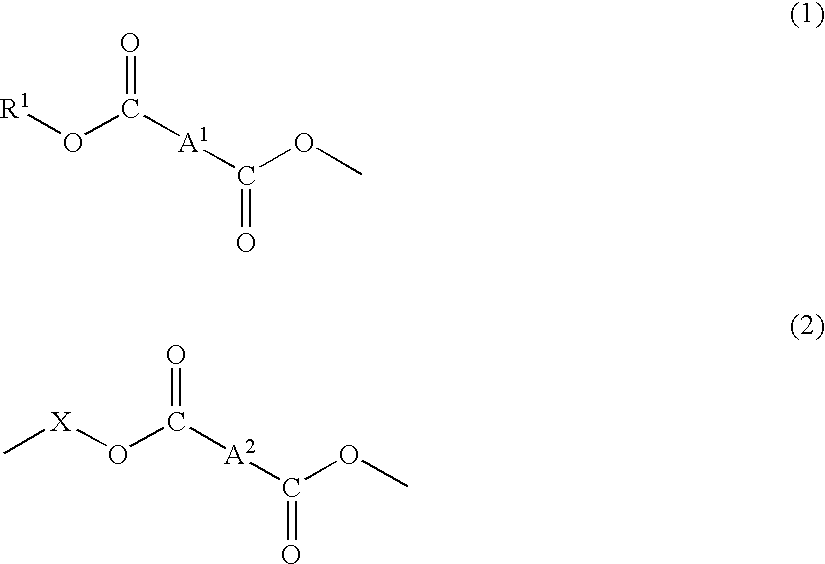
A material for plastic lenses, comprising at least one group represented by the following formula (1) as a terminal group and a group represented by the following formula (2) as a repeating unit. wherein each R1 independently represents an allyl group or a methallyl group, A1 and A2 each independently represents an organic residue derived from a dicarboxylic acid or a carboxylic anhydride, and each X independently represents an organic residue derived from a polyhydric alcohol having from 2 to 3 hydroxyl groups and containing an alicyclic structure within the molecule, provided that by the ester bonding, X can have a branched structure having a group of formula (1) as a terminal group and a group of formula (2) as a repeating unit.

Description

[0001] This application is an application filed under 35 U.S.C. .sctn.111(a) claiming benefit pursuant to 35 U.S.C. .sctn.119(e)(1) of the filing date of the Provisional Application 60 / 218,802 filed Jul. 18, 2000, pursuant to 35 .sctn.111(b).[0002] The present invention relates to a material for plastic lenses, a production process of the material, a plastic lens composition containing the material, a plastic lens obtained by curing the composition, and a production process of the plastic lens.[0003] More specifically, the present invention relates to a plastic lens material which can be used for a plastic lens composition capable of preventing damage to a lens or a mold due to curing shrinkage arising as a problem during the polymerization of a polyethylene glycol poly(allyl carbonate)-based plastic lens material; a production process of the material; a plastic lens composition containing the material; a plastic lens obtained by curing the composition; and a production process of t...

Claims


Application Information

Patent Timeline
Patent Type & Authority Applications(United States)
IPC IPC(8): G02B1/04
CPCG02B1/041C08L31/06
Inventor OOGA, KAZUHIKOASAI, YOSHIFUMIKAI, KAZUFUMITAJIMA, TSUNEOUCHIDA, HIROSHI
Owner SHOWA DENKO KK
Why Eureka
Try Eureka