Floating structure

a floating structure and structure technology, applied in the direction of floating buildings, pontoons, vessel construction, etc., can solve the problems of low wrap resistance of longitudinal bases, relatively high material costs, and inability to approximate arbitrary forms of known bases, so as to achieve the effect of reducing wave resistan

Inactive Publication Date: 2008-10-02
CLEMENT JUERGEN
View PDF15 Cites 1 Cited by
  • Summary
  • Abstract
  • Description
  • Claims
  • Application Information

AI Technical Summary

Benefits of technology

[0006]Accordingly, it is the object of the present invention to provide an improved floatable structure as a rigid unit which especially needs less material.
[0009]In order to attain a high wrap resistance of the floatable structure with as little material use as possible, the connecting members according to the present invention show proper profiles such as a box profile or a hollow triangular profile or a comb-like profile. Preferably, a box profile of ferroconcrete can be used as connecting member. Such a box profile does not only allow for saving of material and thus reduces cost, but it also leads to a weight reduction. Low weight is of particular great importance for floatable structures. For further optimization, additional cross beams can be provided in the interior of the profile.
[0010]Besides the saving of weight, the cavities of the connecting members of the present invention offer the possibility to fill the same with floatable materials like styrofoam. As interior lining, non-corrosive material like synthetic material can also be used as upwelling body provided inside. Thus, a box profile of synthetic material can be inserted which is optionally closed at its ends, whereby a waterproof space is created which can accommodate further equipment. This prevents that larger amounts of water can accumulate inside the connecting members in case of leakiness of the outer walls. The same holds also for the floatable single bodies.
[0012]When working with ferroconcrete, a reinforcement covering for corrosion protection is used which is above 1.5 cm and usually in the range of 2 cm to 5 cm. When choosing the proper reinforcement covering, in addition to standard parameters, also the water composition is to be taken into account for floatable structures. For floatable structures, usually a covering of 4.5 cm or more is used. According to the invention, for the connecting members, carbon fiber or glass fiber material can be used. For textile-reinforced concrete, there is no danger of corrosion in contrast to ferroconcrete. Additionally, by this, a substantially smaller reinforcement covering can be used. This leads to more lightweight constructions and more efficient material use.
[0017]An additional advantage of an equilateral triangle lies in the fact that larger formations can be composed of them without generation of clearances. Thus, arbitrary perimeters can easily be approximated by floatable structures. Nevertheless, designated areas can also be left free to e.g. keep space free for obstacles or building elements like pillars.
[0019]For stabilization, floating single elements can be anchored with one or more holder means to the ground of the water, especially by anchored nylon cables, which are e.g. pre-tensioned with 15 kN. Hereby, vibrations of the structure caused e.g. by waves can efficiently be reduced when choosing the holding positions appropriately. For this purpose, it is particularly appropriate for longitudinal structures that the holder means are attached in a central area of the structure and that they are transverse outwardly wired, respectively. Nylon wires offer the advantage with respect to usual chains that they cannot corrode.

Problems solved by technology

A disadvantage of such a known floating base is that a longitudinal base exhibits either a relatively low wrap resistance or its manufacture is associated with relatively high material costs.
Furthermore, it is disadvantageous that the construction of known bases is not suitable to approximate arbitrary forms, especially rounded forms.

Method used


Image

  • Floating structure
  • Floating structure
  • Floating structure

Examples


Embodiment Construction

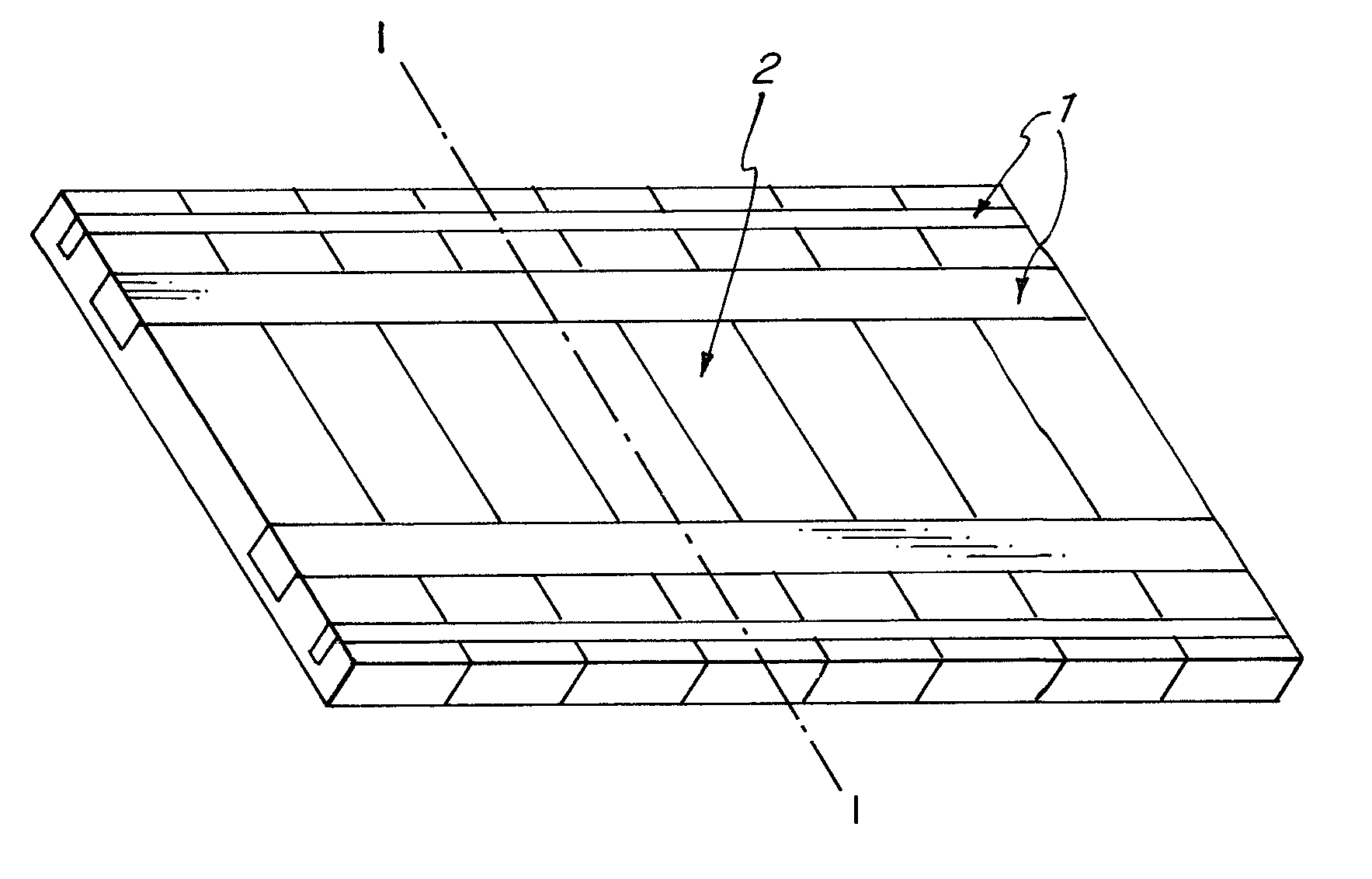
[0025]FIG. 1 is a spatial view of a floatable structure showing the floatable single bodies 2 and the connecting members 1. A plurality of floatable single bodies 2 is provided with cut-outs which are aligned perpendicular to its longer extent and parallel to the water surface. The cut-outs are arranged so that the connecting members 1 can be inserted into them, which then provide for a rigid connection of the single bodies 2. For reduction of wrapping in the floatable structure, preferably more than two, namely for example four connecting elements 1 are used as shown here. Those extend preferably over the total length of the structure.

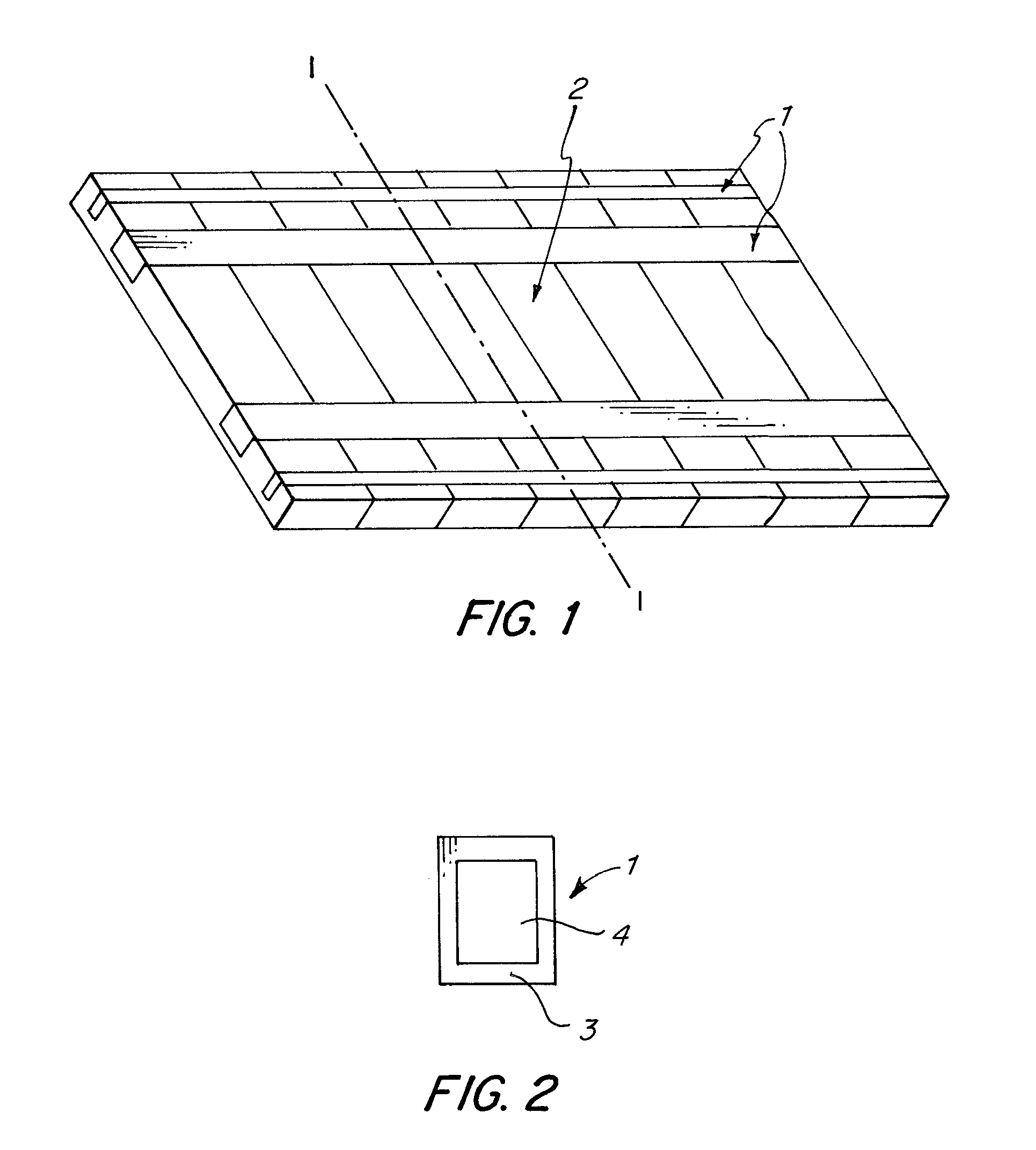
[0026]FIG. 2 is a cross-sectional view of a connecting member 1 of FIG. 1 which shows a box profile 3. The box profile 3 is preferably manufactured of ferroconcrete. First, a U-form is made in the cut-outs of the single bodies 2. The upper plate of the box profile 3 is made later on, which allows to insert styrofoam 4 into the inner space of the box p...


PUM


Abstract

The invention is related to a floatable structure as a rigid unit for carrying loads and especially to such a structure which is composed of floatable single bodies being connected by longitudinal connecting members provided with cavities.

Description

CROSS-REFERENCE TO RELATED APPLICATIONS[0001]The present application is a continuation of pending International patent application PCT / EP2006 / 009105 filed on Sep. 19, 2006 which designates the United States and claims priority from German patent application 10 2005 046 794.6 filed on Sep. 29, 2005, the content of which is incorporated herein by reference.FIELD OF THE INVENTION[0002]The invention relates to a floatable structure as a rigid unit for carrying loads and especially to such a structure which is composed of floatable single bodies being connected with longitudinal connecting members showing cavities.[0003]Floatable structures according to the invention can be used for a plurality of applications, e.g. loads like roads, buildings, commercial facilities, gardens, terraces and objects being hung under the structures like containers for liquids, pipes and walkable premises under water for watching sea animals can be carried.BACKGROUND OF THE INVENTION[0004]In the prior art, a ...

Claims


Application Information

Patent Timeline
Patent Type & Authority Applications(United States)
IPC IPC(8): B63B35/44
CPCB63B3/06B63B35/38B63B35/34
Inventor CLEMENT, JUERGEN
Owner CLEMENT JUERGEN
Why Eureka
Try Eureka