
Packet routing and switching device

a packet-switched computer network and packet-switching technology, applied in data switching networks, multiplex communication, digital transmission, etc., can solve problems such as router performance problems, routers may experience performance problems, and routers may be shut down

Inactive Publication Date: 2008-06-03
CISCO TECH INC
View PDF77 Cites 284 Cited by
  • Summary
  • Abstract
  • Description
  • Claims
  • Application Information

AI Technical Summary

Benefits of technology

[0016]In this manner, by writing data packets to the switching memory (in round-robin order, for instance) after an outgoing link of the router has been assigned to the data packets, the data packets can be quickly extracted from the switching memory for transmission out of the router along the assigned outgoing link.

Problems solved by technology

Conventional routers can suffer from a “denial of service attack” wherein the route processor of a conventional router is interrupted each time a route processor destined packet is received by the router.
If a hacker generates a large number of route processor destined packets to a particular router, then that router may experience performance problems, and possibly shut down, if the route processor is continually interrupted so that it can deal with the receipt and processing of the route processor destined the packets.
It may be problematic for conventional routers to perform the required routing table lookup operations for a series of smaller sized packets flowing into the conventional router at the 40 Gbps line rate without having to drop packets.
If a packet is dropped, then the packet must be retransmitted, which slows the overall message transmission time.
Such an input-striping process makes the initial front end writing process into the buffer memory rather simple, however, it is often difficult to read out the cells and reassemble the cells into a packet because packets are processed out of order in general within the router, which adds latency to the transmission of the packet.

Method used


Image

  • Packet routing and switching device
  • Packet routing and switching device
  • Packet routing and switching device

Examples


Embodiment Construction

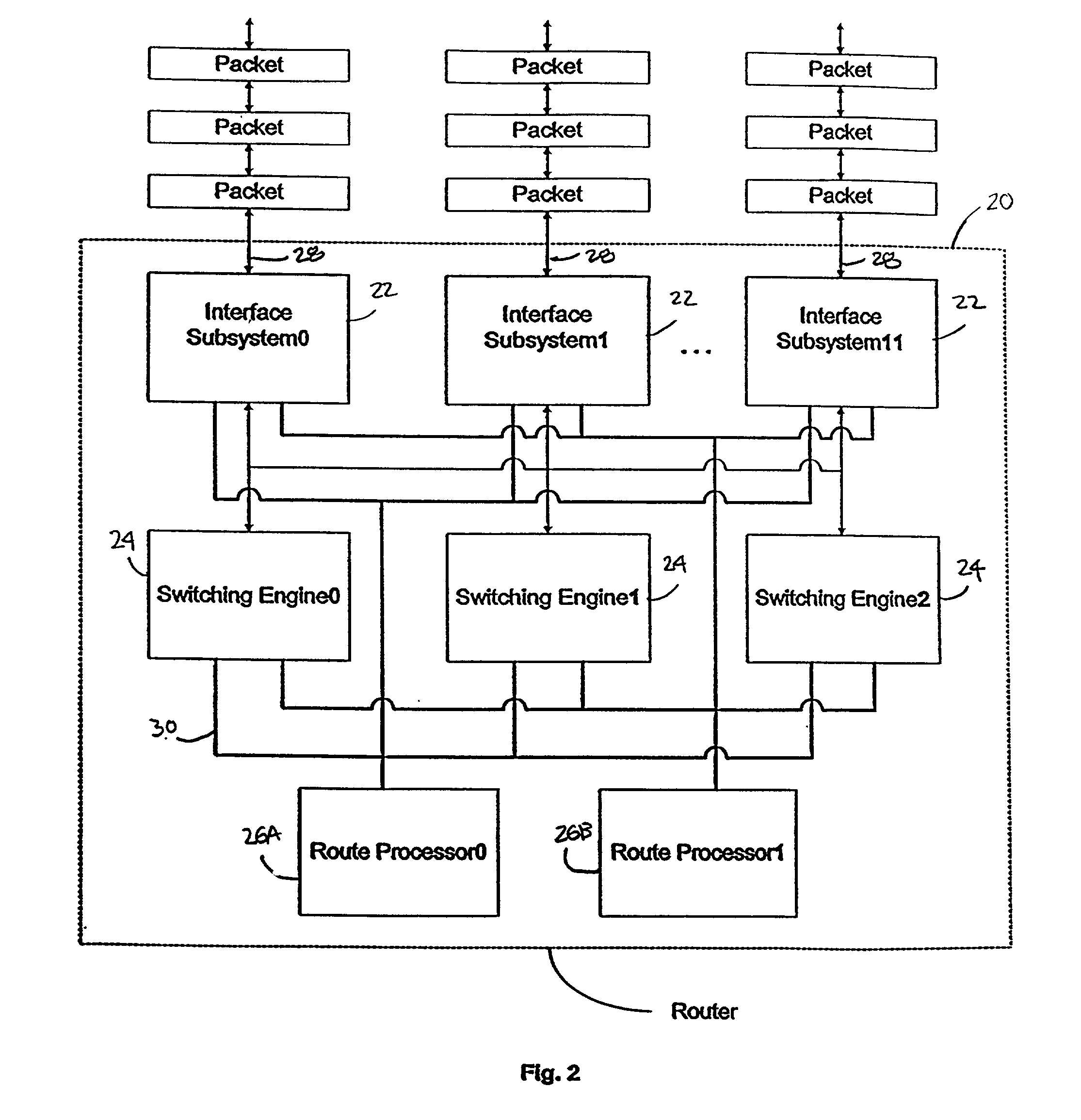
[0082]This detailed description of embodiments of the present invention is subdivided into six sections: section I (“Introduction”); section II (“Method for Routing and Switching a Packet”); section III (“Input-side of the Interface Subsystems”); section IV (“Switching Engine”); section V (“Output-side of the Interface Subsystems”); and, section VI (“Redundancy and Scalability”). The introduction provides a description of components of a router and a description of an architecture for a router, according to various embodiments.

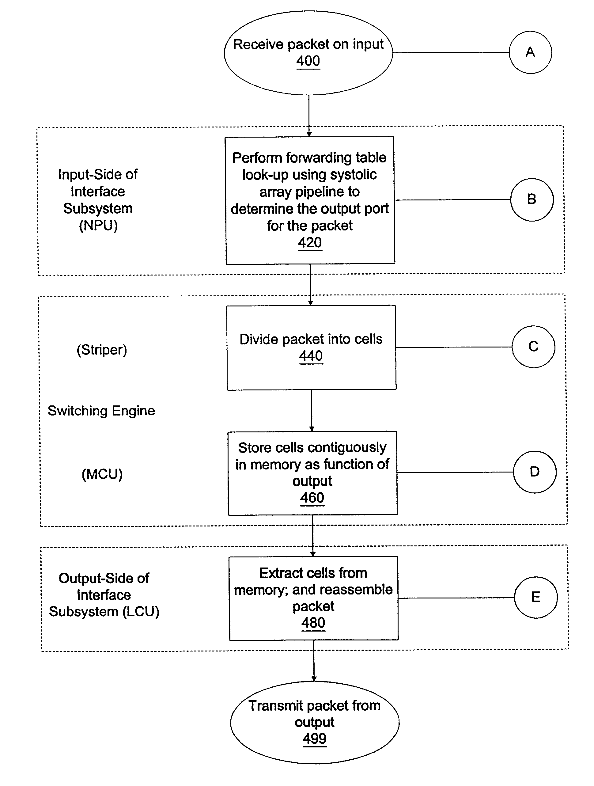
[0083]The second section describes methods of routing and switching a packet, including a discussion of the flow of a packet through a router and various operations performed by a router as the packet flows therethrough. Unlike conventional routers, one example of a method of routing and switching according to the present invention includes performing a forwarding table lookup operation for a packet before the packet is cellified and stored for switching. Acco...


PUM


Abstract

A method for routing and switching data packets from one or more incoming links to one or more outgoing links of a router. The method comprises receiving a data packet from the incoming link, assigning at least one outgoing link to the data packet based on the destination address of the data packet, and after the assigning operation, storing the data packet in a switching memory based on the assigned outgoing link. The data packet extracted from the switching memory, and transmitted along the assigned outgoing link. The router may include a network processing unit having one or more systolic array pipelines for performing the assigning operation.

Description

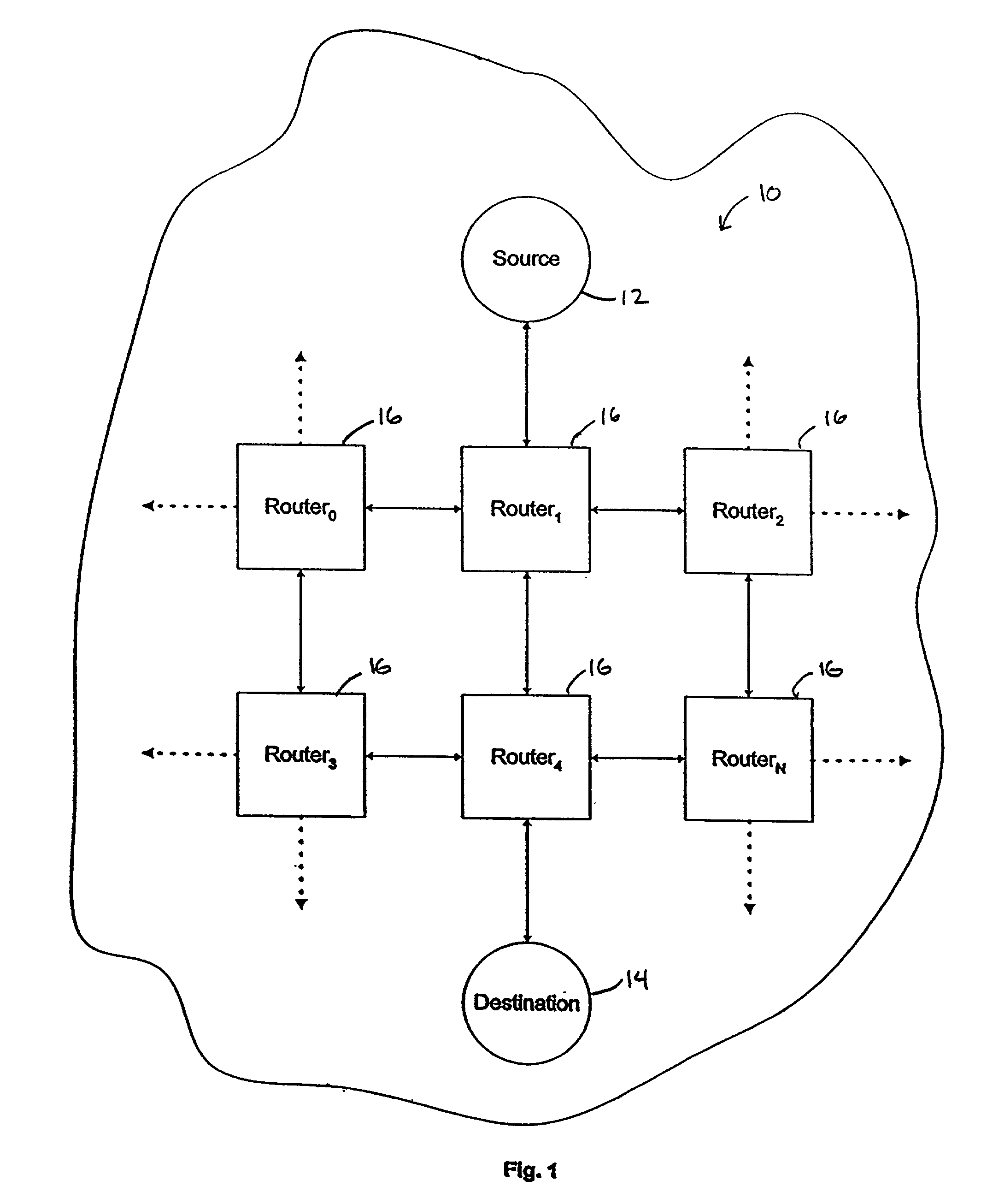
CROSS-REFERENCE TO RELATED APPLICATION[0001]This application claims priority under 35 U.S.C. 119(e) to U.S. provisional patent application entitled “PACKET ROUTING AND SWITCHING DEVICE,” Ser. No. 60 / 309,042 filed Jul. 30, 2001, the disclosure of which is hereby incorporated by reference in its entirety. This application is also related to the co-pending, commonly assigned patent application entitled “PROCESSING UNIT FOR EFFICIENTLY DETERMINING A PACKET'S DESTINATION IN A PACKET-SWITCHED NETWORK,” filed on Jul. 30, 2001, Application No. 60 / 309,087, the disclosure of which is hereby incorporated by reference in its entirety.FIELD OF THE INVENTION[0002]This invention relates, in general, to network routers, and more particularly to a device for performing routing and switching in a packet-switched computer network.BACKGROUND OF THE INVENTION[0003]Computer networks often use packet-switching for transmitting messages, such as web pages and e-mail, along a path between a source and a des...

Claims


Application Information

Patent Timeline
IPC IPC(8): H04L12/28
CPCH04L12/66H04L69/12H04L69/22
Inventor BARNES, PETER M.JAYARAM, NIKHILLI, ANTHONY J.LYNCH, WILLIAM L.MEHROTRA, SHARAD
Owner CISCO TECH INC
Learn More