Wavelength dispersion compensation design method and a system thereof

a design method and wavelength dispersion compensation technology, applied in the field of wavelength dispersion compensation design methods and systems, can solve the problems of difficult to design the network in a short period, the method of optimizing the amount of wavelength dispersion compensation for any desired point-to-point transmission system and metro system of a ring structure is not available in a commonly applicable and formulized manner, and achieves the effect of shortening the design tim

Inactive Publication Date: 2008-06-03
FUJITSU LTD
View PDF11 Cites 6 Cited by
  • Summary
  • Abstract
  • Description
  • Claims
  • Application Information

AI Technical Summary

Benefits of technology

[0025]According to the wavelength dispersion compensation design method, a commonly applicable and formulized method of optimizing the amount of wavelength dispersion compensation is realized for a point-to-point transmission system and a ring-structured system, thereby shortening the design time.

Problems solved by technology

That is, a method of optimizing the amount of the wavelength dispersion compensation for any desired point-to-point transmission systems and metro systems of a ring structure is not available in a commonly applicable and formulized manner.
For this reason, when designing an optical network, various design methods have to be used depending on link form, making it difficult to design the network in a short period.

Method used


Image

  • Wavelength dispersion compensation design method and a system thereof
  • Wavelength dispersion compensation design method and a system thereof
  • Wavelength dispersion compensation design method and a system thereof

Examples


first embodiment

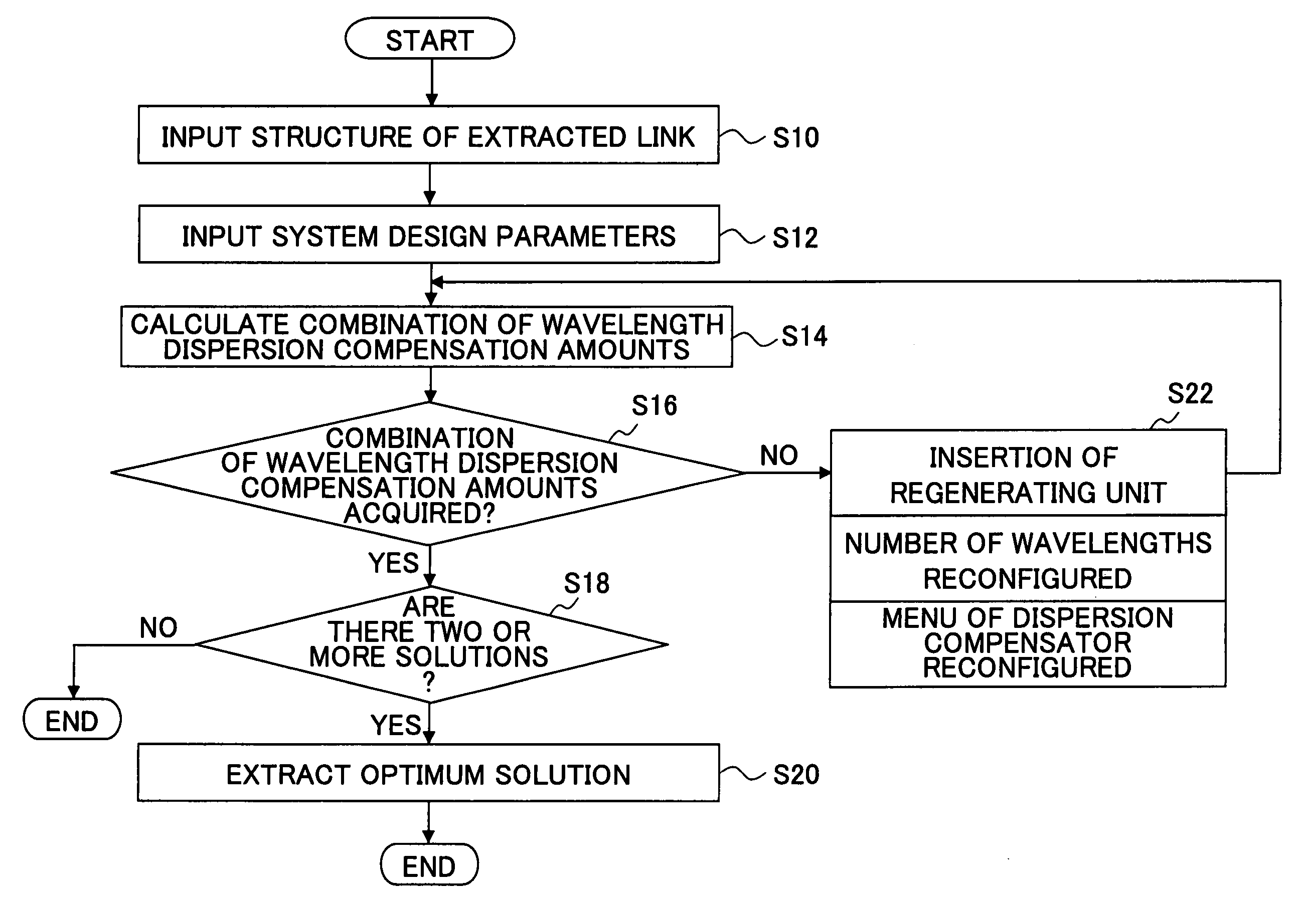
[0062]Next, the first embodiment is described, wherein a wavelength dispersion compensation design is performed for a link that is extracted from an optical network as shown in FIG. 6. Here, the extracted link is from a node N10 (point A) to a node N13 (point B) as indicated by a thick line. The extracted link consists of three spans P11, P12, and P13 that connect the starting node N10 and the terminating node N13, and nodes N11 and N12 that are each equipped with OADM functions as shown in FIG. 7.

[0063]The spans P11 through P13 include wavelength dispersion compensators 221 through 223, respectively, and wavelength dispersion compensators 241 through 243, respectively. Here, the first wavelength dispersion compensators 221 through 223 are connected on the upper stream side of the corresponding spans, the latter ones being provided on the down stream side of the corresponding spans. Then, the total amount Dd(n) of wavelength dispersion compensation for each span is expressed as Dd(n...

second embodiment

[0095]Next, the second embodiment is described with reference to FIG. 11, which is a ring configuration system. The ring system includes four spans P21 through P24, and nodes N20 through N23 each having OADM functions. There is no regenerating unit among the nodes N20 through N23.

[0096]In this case, if the node N20, for example, serves as the starting node and the terminating node, Paths are conceived as shown in FIG. 12. Paths are extracted by making each node into the starting node and the terminating node, and Paths (1) through (13) are obtained as shown in FIG. 12. Here, Path (1) that starts at the node N20 and returns to the node N20 may be defined as not existing. In this case, the number of the Paths is 12, and 12 simultaneous inequalities are to be solved for obtaining the amounts of wavelength dispersion compensation of the spans.

[0097]Where “i” represents a node number, “s” represents the number of the spans, and “M” represents the number of spans to which a dispersion com...

third embodiment

[0099]Next, the third embodiment is described with reference to FIG. 13, which is another ring configuration system and is equipped with a regenerating unit. The ring system includes four spans P31 through P34, and three nodes N31 through N33 each have an OADM function, while the node N30 is a regenerating unit (Reg).

[0100]At this time, the node N30 is made into the starting node and the terminating node, and Paths are developed as shown in FIG. 14. As shown in FIG. 14, Paths (1) through (10) are extracted. Here, Path (1) starting at N30 and terminating at N30 can be defined as not existing. In this case, the number of Paths is nine, and nine simultaneous inequalities are to be solved to obtain the amounts of wavelength dispersion compensation of the spans.

[0101]Where “i” represents a node number, “s” represents the number of the spans, and “M” represents the number of spans to which a dispersion compensator is provided, concerning the formulas (1) and (2), the number of simultaneou...


PUM


Abstract

The present invention discloses a design method of wavelength dispersion compensation of a desired link that is extracted from an optical network, the link including two or more spans, and two or more nodes (N1, N4) that are equipped with an add / drop function, as shown in FIG. 2. All residual dispersion ranges of paths that reach corresponding nodes are adjusted to fall within predetermined tolerable residual dispersion ranges that are set up for all the paths of the link by adjusting wavelength dispersion compensators provided to each of the spans.

Description

CROSS-REFERENCE TO RELATED APPLICATION[0001]This application is a U.S. continuation application filed under 35 USC 111(a) claiming benefit under 35 USC 120 and 365(c) of PCT application JP2003 / 008797, filed Jul. 10, 2003. The foregoing application is hereby incorporated herein by reference.BACKGROUND OF THE INVENTION[0002]1. Field of the Invention[0003]The present invention generally relates to a wavelength dispersion compensation design method, and a system thereof; and especially relates to a wavelength dispersion compensation design method for compensating for a wavelength dispersion generated in an optical transmission system, and a design system thereof.[0004]2. Description of the Related Art[0005]When planning a wavelength division multiplexing (WDM) optical transmission system with a transmission speed of 10 Gbps, it is required that an optical network be designed at low cost in a short period, the importance of which will increase with a WDM optical transmission system with ...

Claims


Application Information

Patent Timeline
Patent Type & Authority Patents(United States)
IPC IPC(8): H04B10/08H04B10/00H04B10/12H04J14/02H04B10/2507H04B10/2525H04B10/27H04B10/29H04J14/00
CPCH04B10/2513
Inventor AKIYAMA, YUICHITERAHARA, TAKAFUMIHOSHIDA, TAKESHINAKASHIMA, HISAO
Owner FUJITSU LTD
Why Eureka
Try Eureka