Switching power supply

a power supply and switch technology, applied in the direction of power conversion systems, dc-dc conversion, instruments, etc., can solve problems such as the destruction of the power supply system, and achieve the effect of high speed current control and high precision

Inactive Publication Date: 2008-06-10
RENESAS ELECTRONICS CORP
View PDF8 Cites 164 Cited by
  • Summary
  • Abstract
  • Description
  • Claims
  • Application Information

AI Technical Summary

Benefits of technology

[0007]Accordingly, an object of the present invention is to provide a switching power supply apparatus that can precisely detect current, without being subject to influences of offset of a operational amplifier for current sensing, and further can make the operational amplifier for current sensing structured of a single power supply, and thereby can attain a highly precise and high speed current control.
[0012]According to the method, since the influences due to offset voltage of the single power supply operational amplifier can be avoided, the source potential or the emitter voltage of a current sensing MOS transistor can be precisely kept at the source potential or the emitter voltage of the low side power MOS transistor, and accordingly, with regard to the source potential or the emitter voltage of the current sensing MOS transistor, the potential does not change by the offset voltage of the current sensing operational amplifier like in the prior art, and the current sensing precision is improved to a switching power supply apparatus and a power supply driver circuit and the output current of a module.
[0015]That is, according to the present invention, the influence of displacement of virtual ground potential due to offset of the current sensing operational amplifier is controlled, it is possible to realize a switching power supply apparatus that can precisely detect current, without being subject to influences of offset of a operational amplifier for current sensing, and further can make the operational amplifier for current sensing structured of a single power source, and thereby can attain a highly precise and high speed current control.

Problems solved by technology

In such a power supply system, if the currents flowing in respective power supplies (phases) are not uniform, heat generation concentrates and causes destruction of the power supply system.

Method used


Image

  • Switching power supply
  • Switching power supply
  • Switching power supply

Examples


first embodiment

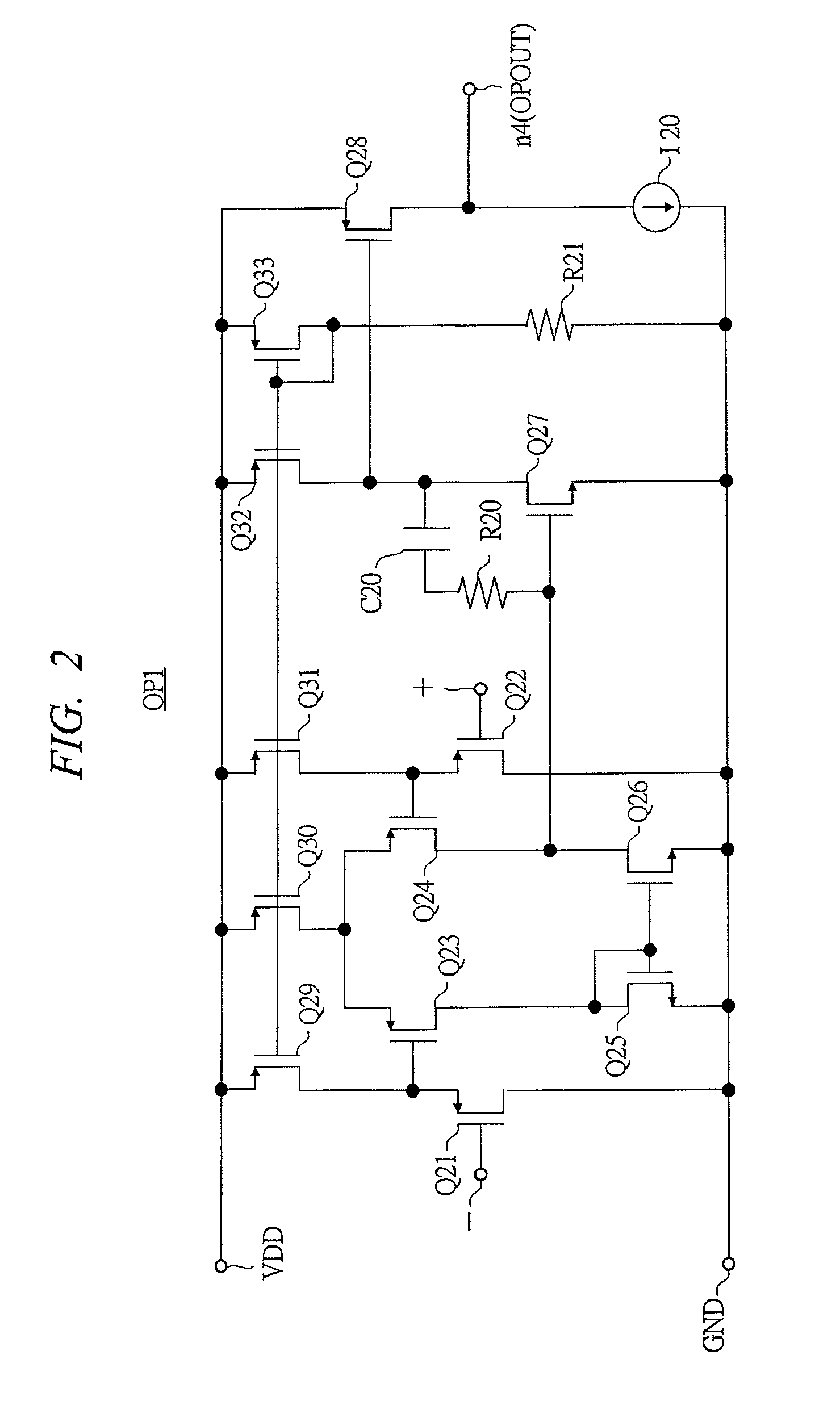
[0032]With reference to FIGS. 1-4, an example of a switching power supply apparatus according to a first preferred embodiment of the present invention is explained hereinafter.

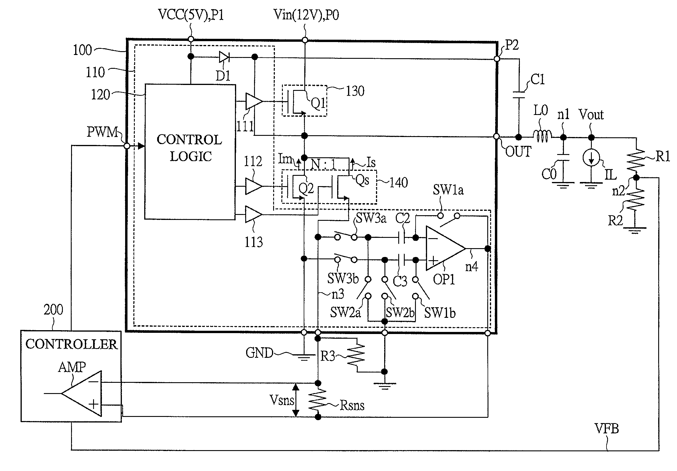
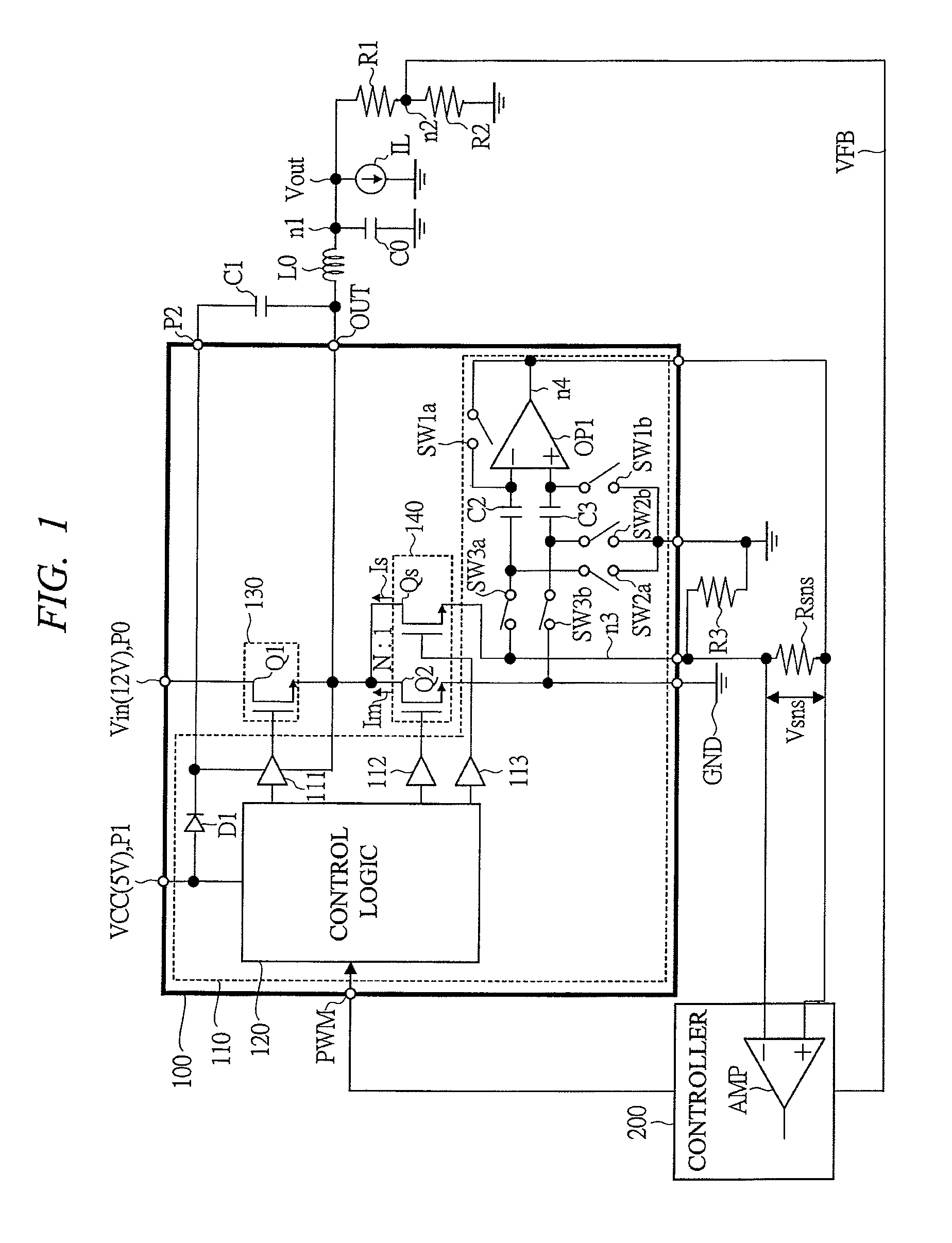
[0033]FIG. 1 is a circuit structural diagram showing a structural example of a switching power supply apparatus according to the first preferred embodiment.

[0034]The switching power supply apparatus according to the first preferred embodiment is to be applied to, for example, a power supply driver module incorporating a power supply driver circuit and a step down type switching regulator to which the same is applied, and incorporates a power supply driver module 100 that has a pair of power MOS transistors Q1 (hereinafter, high side power MOS transistor), and Q2 (hereinafter, low side power MOS transistor) connected in series between a voltage input terminal P0 to which DC voltage Vin (for example 12V) supplied from a DC power supply such as a battery or the like is input and a ground point (GND), and a driver...

second embodiment

[0064]With reference to FIG. 5, an example of a switching power supply apparatus according to a second preferred embodiment of the present invention is explained hereinafter. Meanwhile, the structure of the switching power supply apparatus according to the present preferred embodiment, the structure of the current sensing operational amplifier are same as those in the first preferred embodiment (FIGS. 1 and 2), therefore explanations thereof are omitted herein.

[0065]FIG. 5 is a timing chart showing changes of respective elements, or node potential and current, in a switching power supply apparatus according to present preferred embodiment.

[0066]In the switching power supply apparatus according to present preferred embodiment, in a case where operated at the timing in the first preferred embodiment (FIG. 3), when the time for which the high side power MOS transistor Q1 is in its ON state is very short, if the time enough for potential of the same size as the offset voltage of the cur...

third embodiment

[0069]With reference to FIG. 6, an example of a switching power supply apparatus according to a third preferred embodiment of the present invention is explained hereinafter.

[0070]FIG. 6 is a circuit structural diagram showing a structural example of main part of a switching power supply apparatus according to the present preferred embodiment.

[0071]The switching power supply apparatus according to the present preferred embodiment has a shortcircuited structure, where a source terminal and a drain terminal of an auxiliary MOS transistor Q3 of roughly half the size of the MOS used in the changeover switch SW1a of the inverting input terminal of the current sensing operational amplifier OP1 in FIG. 1 of the first preferred embodiment are connected, and the inverting signal of the changeover switch SW1a is connected to the gate drive signal of the auxiliary MOS transistor Q3, and the offset cancel capacitor C3 of the non inverting input terminal of the current sensing operational amplifi...


PUM


Abstract

In a switching power supply apparatus for performing a switching control of a power MOS transistor that flows current to a coil and converting input voltage into output voltage, even if there occurs offset voltage in a current sensing operational amplifier, source potential of a current sensing MOS transistor is precisely kept at source potential of a low side power MOS transistor. For example, an offset cancel capacitor is arranged at an inverting input terminal of the current sensing operational amplifier, and voltage in the direction to offset the offset voltage occurring in the operational amplifier is charged to this capacitor.

Description

CROSS-REFERENCE TO RELATED APPLICATION[0001]The present application claims priority from Japanese Patent Application No. JP 2006-003765 filed on Jan. 11, 2006, the content of which is hereby incorporated by reference into this application.TECHNICAL FIELD OF THE INVENTION[0002]The present invention relates to an art of a power supply apparatus for generating DC voltage, more specifically to an art effective when applied to a current sensing circuit of a switching power supply apparatus that performs switching control by for example PWM (Pulse Width Modulation) method and converts input voltage and obtains output voltage, in current sensing in a switching regulator.BACKGROUND OF THE INVENTION[0003]In recent years, many electronic apparatuses have a micro processor (hereinafter, referred to as CPU) as a system controller. Further, the operating frequency of the CPU has become higher, and as the operating frequency is increasing, so the maximum operating current is increasing.[0004]Unde...

Claims


Application Information

Patent Timeline
Patent Type & Authority Patents(United States)
IPC IPC(8): G05F1/00G05F1/575G05F1/618
CPCH02M3/156H02M2001/0009H02M1/0009H03K2217/0027
Inventor ISHIGAKI, TAKUYASASE, TAKASHIKANOUDA, AKIHIKOTATENO, KOJIKUDO, RYOTARO
Owner RENESAS ELECTRONICS CORP
Why Eureka
Try Eureka