Method for controlling an internal combustion engine using valve lift switchover

a technology of internal combustion engine and valve lift, which is applied in the direction of electric control, braking system, instruments, etc., can solve the problems of valve lift switchover, differences in torque, and difficulty in respect of torque neutrality of internal combustion engine, so as to save computing power and/or memory storage capacity overall, and the effect of greater precision

Active Publication Date: 2008-06-10
VITESCO TECH GERMANY GMBH
View PDF5 Cites 8 Cited by
  • Summary
  • Abstract
  • Description
  • Claims
  • Application Information

AI Technical Summary

Benefits of technology

[0008]It is therefore an object of the present invention to provide a method for controlling an internal combustion engine using valve lift switchover which is characterized by an improved torque neutrality during valve lift switchover processes in comparison with the prior art.
[0019]According to a further embodiment the detailed intake manifold model is executed with greater precision than the basic intake manifold model in respect of the determination of the cylinder charge in order to save computing power and / or memory storage capacity overall.

Problems solved by technology

A continuing problem with this technology continues to be the valve lift switchover process as such.
Switching from a small to a large valve lift in particular creates difficulties in respect of the torque neutrality of the internal combustion engine.
However, even small errors in the model calculation lead to differences in torque and consequently to inaccuracies in the valve lift switchover.
A further problem at this juncture is that the combustion-related behavior of the internal combustion engine usually changes as a result of the valve lift switchover.
A further problem arises if, in the course of the valve lift switchover, a change in combustion behavior takes place, for example when a spark-ignition combustion process transitions to a controlled self-ignition.
However, the problem here is that the complexity of the models increases rapidly if all the parameters influencing a quantity to be mapped are to be recorded with a particular precision.
Even modern engine management systems quickly reach their limits at this point.
In this case the memory storage capacity and computing capacity of the engine management system are rapidly exhausted, with the result that ultimately compromises and sacrifices have to be made with regard to precision.

Method used


Image

  • Method for controlling an internal combustion engine using valve lift switchover
  • Method for controlling an internal combustion engine using valve lift switchover
  • Method for controlling an internal combustion engine using valve lift switchover

Examples


Embodiment Construction

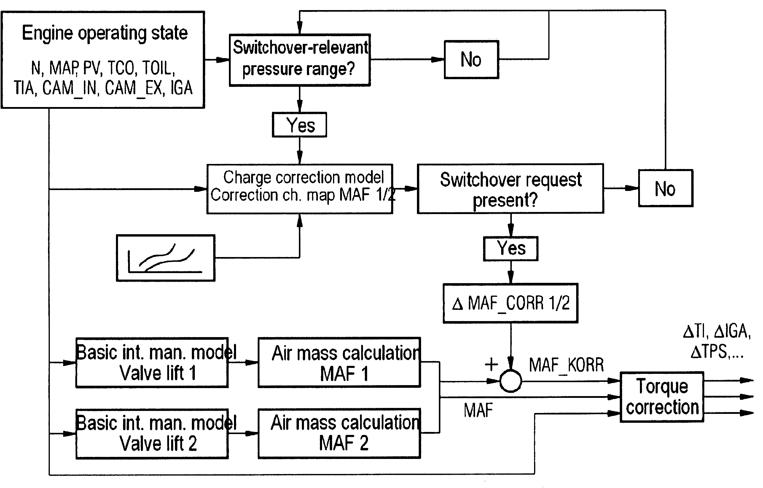
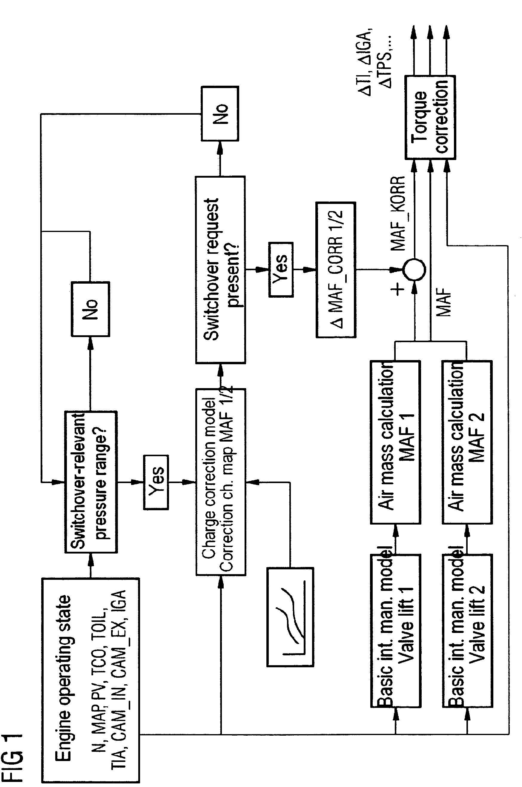
[0023]One embodiment of the present invention is shown in FIG. 1. This depicts a flow diagram of the method for valve lift switchover which is executed within the engine management system of the internal combustion engine. The basis for this method is formed by the internal combustion engine's operating data which is recorded and forwarded to the engine management system. Said data includes, among other variables, the engine speed N, the accelerator pedal value PV, the intake manifold pressure MAP, the coolant temperature TCO, the oil temperature TOIL, the intake air temperature TIA, camshaft signals CAM_IN, CAM_EX and the cylinder-specific overall ignition angle IGA.

[0024]The recorded intake manifold pressure MAP preferably forms the starting point for controlling the switchover of the valve lift as a function of the operating state of the internal combustion engine. By way of example the valve lift is switched over between the discrete valve lift 1 and the discrete valve lift 2. I...


PUM


Abstract

In one aspect, a method for controlling an internal combustion engine using valve lift switchover is provided. Within the scope of this method, a switchover intake manifold model for the switchover-relevant pressure range for valve lift switchover is applied in addition to the use of a basic intake manifold model. This ensures a valve lift switchover with approximately constant torque of the internal combustion engine.

Description

CROSS REFERENCE TO RELATED APPLICATIONS[0001]This application claims priority of German application No. 102005048703.3 DE filed Oct. 11, 2005, which is incorporated by reference herein in its entirety.FIELD OF INVENTION[0002]The present invention relates to a method for controlling an internal combustion engine using valve lift switchover, in particular using discrete valve lift switchover.BACKGROUND OF INVENTION[0003]The principle of valve lift switchover in internal combustion engines is known in the prior art. Thus, for example, systems such as Porsche's Vario Cam Plus have already been in series production for some years (see also “Handbuch Verbrennungsmotor” (“Combustion engine manual”), editor: van Basshuysen / Schäfer, published by Vierweg Verlag, 1st edition, April 2002). A continuing problem with this technology continues to be the valve lift switchover process as such. Switching from a small to a large valve lift in particular creates difficulties in respect of the torque ne...

Claims


Application Information

Patent Timeline
Patent Type & Authority Patents(United States)
IPC IPC(8): B60T7/12G06F17/00F01L1/34
CPCF02D13/0207F02D41/0002F02D2041/001F02D2200/0402Y02T10/42Y02T10/18Y02T10/12Y02T10/40F02D13/02F01L13/00F02D41/18
Inventor BAUER, ERWINELLMER, DIETMARKLINGSEIS, BERNHARD
Owner VITESCO TECH GERMANY GMBH
Why Eureka
Try Eureka