Heat generator

a heat generator and heat source technology, applied in the field of heat generators, can solve the problems of wasting interior space and affecting the efficiency of operation, and achieve the effect of positive performan

Inactive Publication Date: 2008-06-17
THOMA CHRISTIAN
View PDF45 Cites 42 Cited by
  • Summary
  • Abstract
  • Description
  • Claims
  • Application Information

AI Technical Summary

Benefits of technology

[0010]It is a further preferred feature of the present invention that the rotational energy imparted to the viscous fluid by the rotating rotor / drive shaft causes a radially outwardly displacement of the viscous fluid from the interior of the rotor / drive shaft. Any air or inert gas that might be present in the heat generating region during operation is more likely to remain nearer the interior of the rotor / drive shaft and away from the rotor exterior surface where it might lessen the performance of the device.
[0012]For certain applications, there may be an advantage if any entrained air carried by the viscous fluid can be removed prior to the viscous fluid being poured into the heat generating chamber. By incorporating such an expanding and contracting element into the heat generating chamber, the entire volumetric space of the heat generating chamber may as a result be usefully employed to carry a full capacity of viscous fluid without the need to fit either a fluid level regulating valve or air pocket space to cope with fluid volume expansion due to a rise in fluid temperature. Equally, the lack of air or inert entrained in the viscous fluid is likely to result in a more positive performance.

Problems solved by technology

Hydraulic systems with flow control devices operating without fluid filtration have been know to be troubled by fluid borne contamination, especially when surfaces become scoured should abrasive material reach in-between the sliding surfaces, causing leakage.
As a consequence, some interior space is wasted due to there being provision for an air or inert gas pocket and as a result, and performance during operation may be lower than with the earlier type described in U.S. Pat. No. 6,152,084 due to the mixing of the gas with the viscous fluid during operation.

Method used


Image

  • Heat generator
  • Heat generator
  • Heat generator

Examples


Embodiment Construction

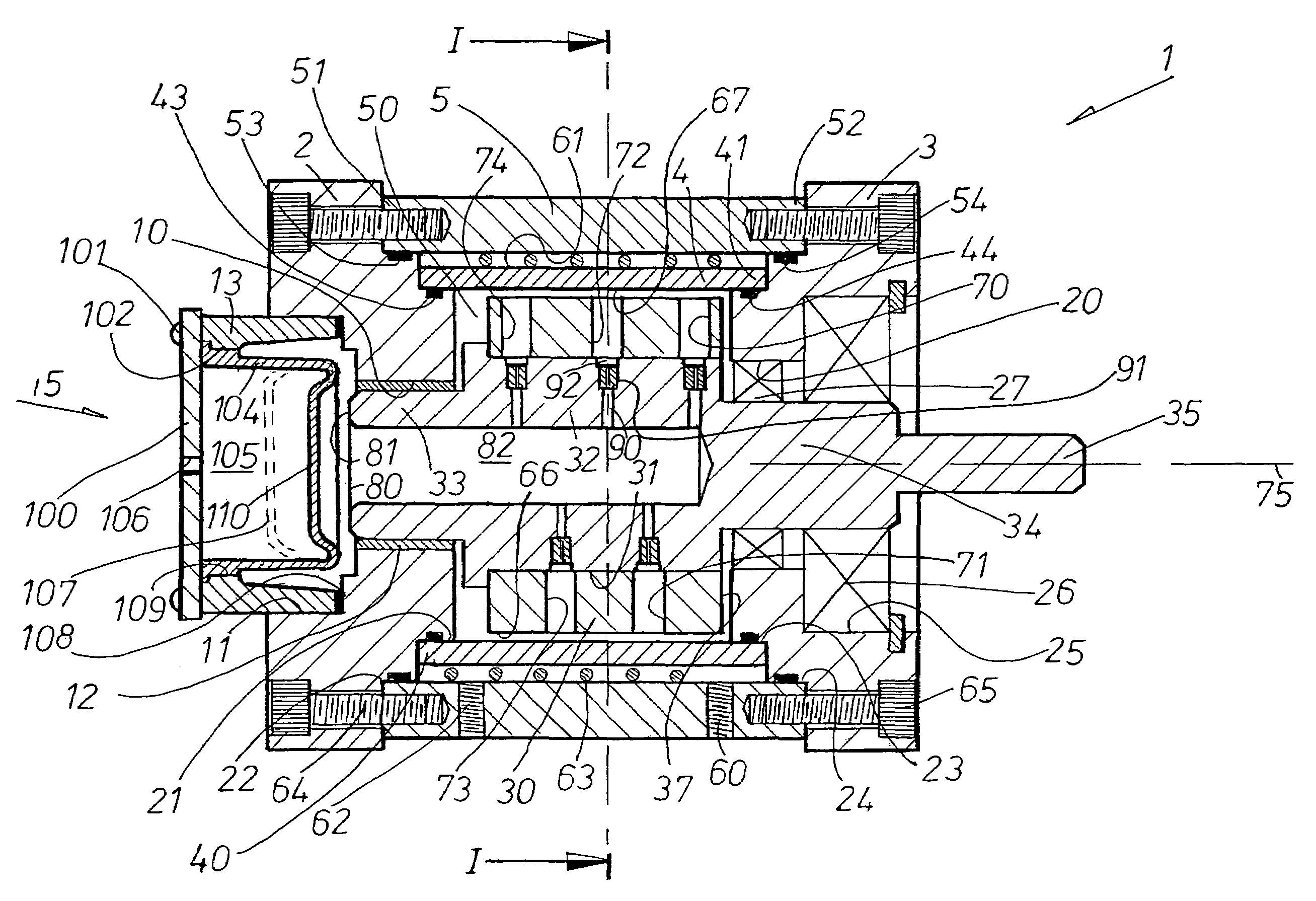
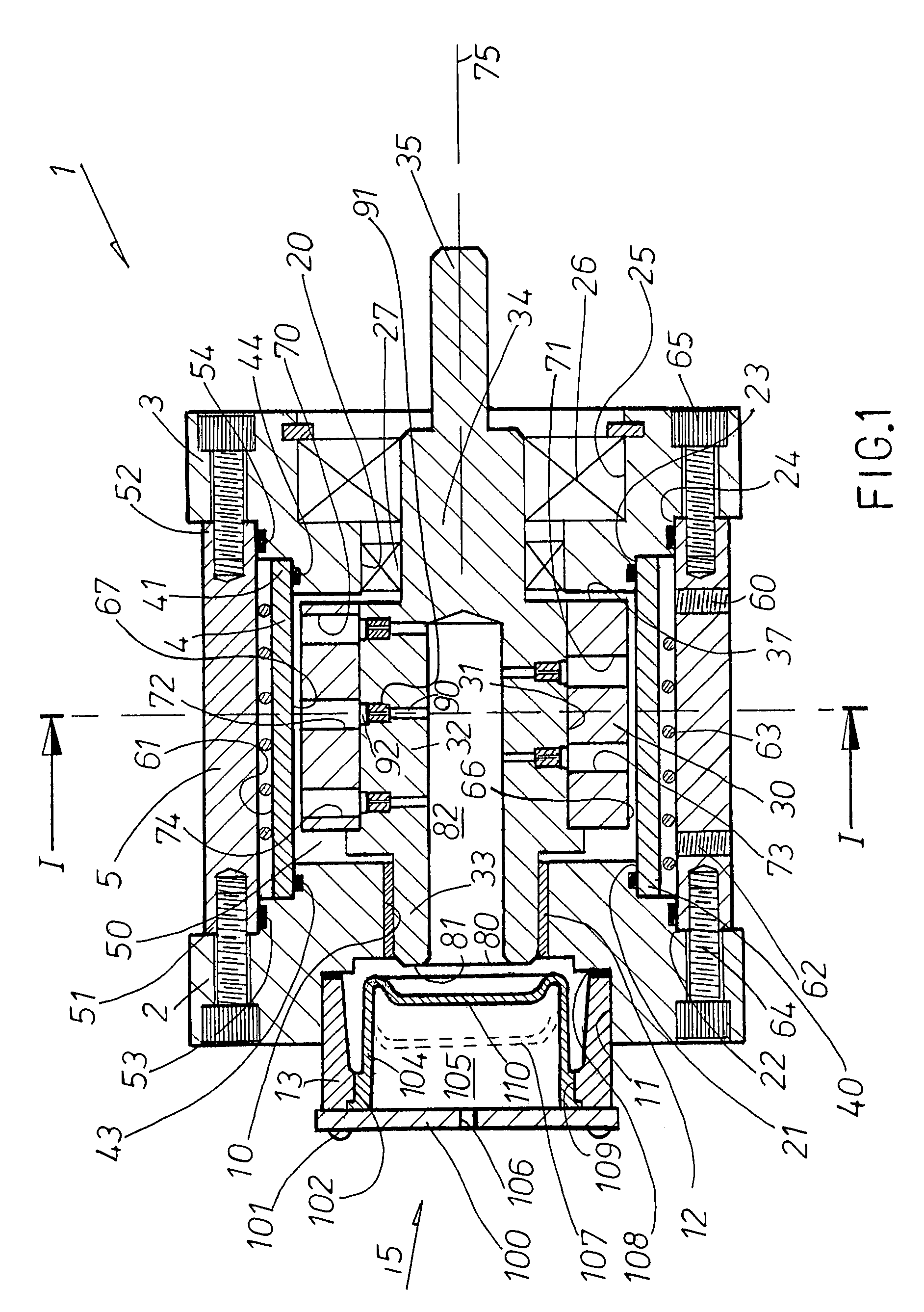
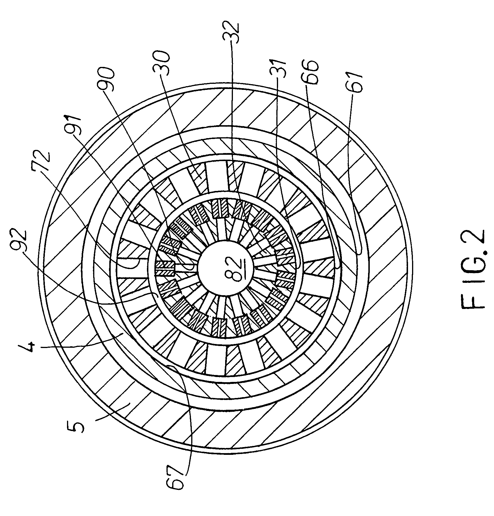
[0029]Referring to FIGS. 1 and 4, the device denoted by reference numeral 1 shows an entire housing structure comprising four members, a rear housing member 2, a front housing member 3, a sleeve member 4 surrounded by an outer jacket member 5. Rear housing member 2 is provided with a stepped central bore shown as 10, 11, and where a bearing 12 is disposed in the smaller sized bore 10 and part of the housing portion 13 of the deformable element indicated by reference numeral 15 is threaded into bore 11. A pair of registration shoulders 21, 22 are located on rear housing element 2 and a complementary pair of registration shoulders 23, 24 is provided on front housing element 3. Front housing element 3 is provided with a stepped central bore shown as 20, 25, and where a bearing 26 is disposed in bore 25 and a seal 27 in bore 20. The rotatable unit for this embodiment is shown comprising a rotor portion 30 seated, preferably as a heat shrink fit, on the diameter 31 of the central drive s...


PUM


Abstract

An apparatus for the heating of a viscous fluid contained in a heat generating chamber by a rotatable unit having a fluid shearing surface formed on a face thereof, the unit by shearing of the viscous fluid on that face induces the heating of said viscous fluid and where an external heat extracting surface is provided for this heat to be removed by a further fluid in contact with that surface. The two dissimilar fluids are kept apart by at least the housing acting as a fluid partition. The unit has an interior space as a storage location for viscous fluid with a deformable element for volume changes of the viscous fluid during the operation of the apparatus.

Description

BACKGROUND OF THE INVENTION[0001]This invention relates to a heat generator, typically employed in automobiles, the generator having an operating chamber defined in a housing, a rotor disposed inside the housing and driven by a shaft which is connected to some form of driving machine like the vehicle engine or an electric motor. The operating chamber contains a viscous fluid and where heat generated by the rotor rotating in the viscous fluid can be extracted from the generator by passing another fluid across the surface of the housing, typically by means of an annular passageway formed between the housing and a surrounding housing jacket through which heat extracting fluid flows. Therefore the operating chamber of the generator is the heat generating chamber containing the viscous fluid whereas the annular passageway is the heat radiating chamber through which the heat exchanging fluid such as engine coolant is arranged to pass through, and which, for instance, can be piped to the p...

Claims


Application Information

Patent Timeline
Patent Type & Authority Patents(United States)
IPC IPC(8): B60H1/02F24D1/00F24J3/00
CPCF24J3/003F24V40/00
Inventor THOMA, CHRISTIAN
Owner THOMA CHRISTIAN
Why Eureka
Try Eureka