Electric contact and female terminal

a technology of electric contact and female terminal, which is applied in the direction of coupling contact members, coupling device connections, electrical apparatus, etc., can solve the problems of limit in downsizing components, and achieve the effect of stable electrical connection and high curren

Inactive Publication Date: 2008-06-17
HITACHI CABLE
View PDF22 Cites 61 Cited by
  • Summary
  • Abstract
  • Description
  • Claims
  • Application Information

AI Technical Summary

Benefits of technology

[0006]In the prior art, the contact resistant is required to be reduced by applying a large force between the male contact maker 53 and the female contact maker 52 by way of spring force of the electric contact 54 in order to carry the high current, and a material having a high electric conductivity is required to be used for reducing the heat generation of the electric contact 54 itself.
[0020]According to the present invention, it will be appreciated that the spring elasticity characteristic and the electric conductivity characteristic can be controlled individually which cannot be attained by using a single material. As a result, more stable electrical connection can be secured between the male contact maker and the female contact maker in order to carry the high current.

Problems solved by technology

However, any means is required for reducing the heat generation and the arc discharge when carrying the current, and in case that those phenomena occur, there may be such bad influences that the case of the connector melts down and that the thermal effect transfers to the environment components.
However, those materials have an electric conductivity lower than approximately 50% IACS, and require a larger volume for the electric contact 54 for carrying the high current, which results in a limit in downsizing the components.

Method used


Image

  • Electric contact and female terminal
  • Electric contact and female terminal
  • Electric contact and female terminal

Examples


Embodiment Construction

[0031]By referring to attached drawings, the best mode for embedding the present invention is described.

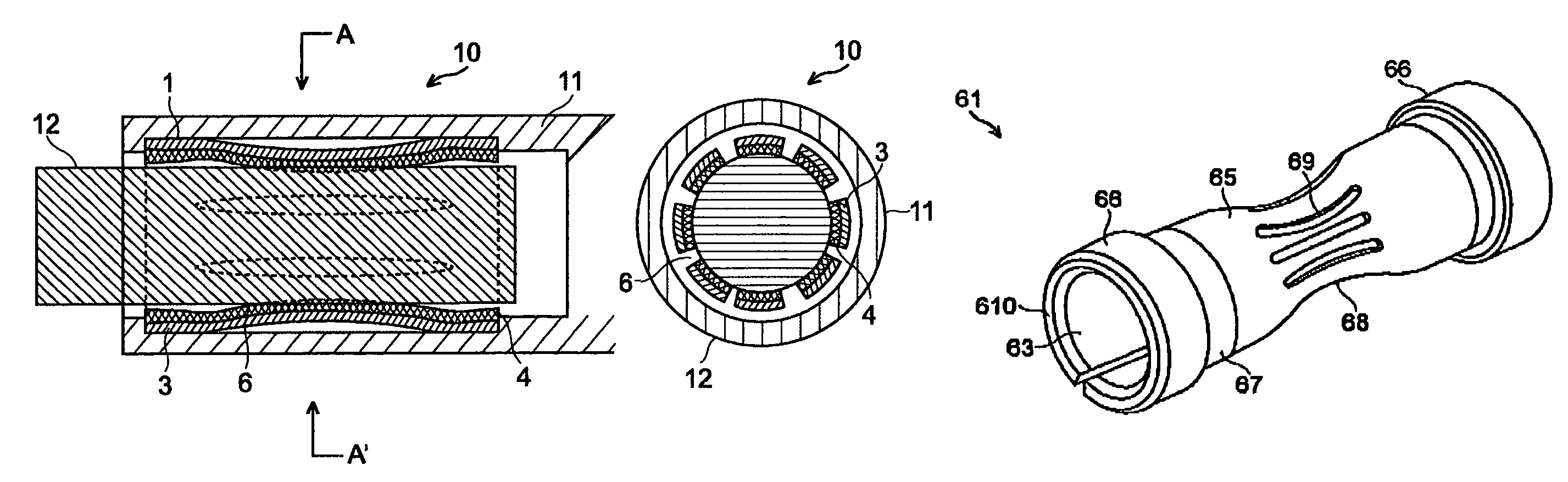
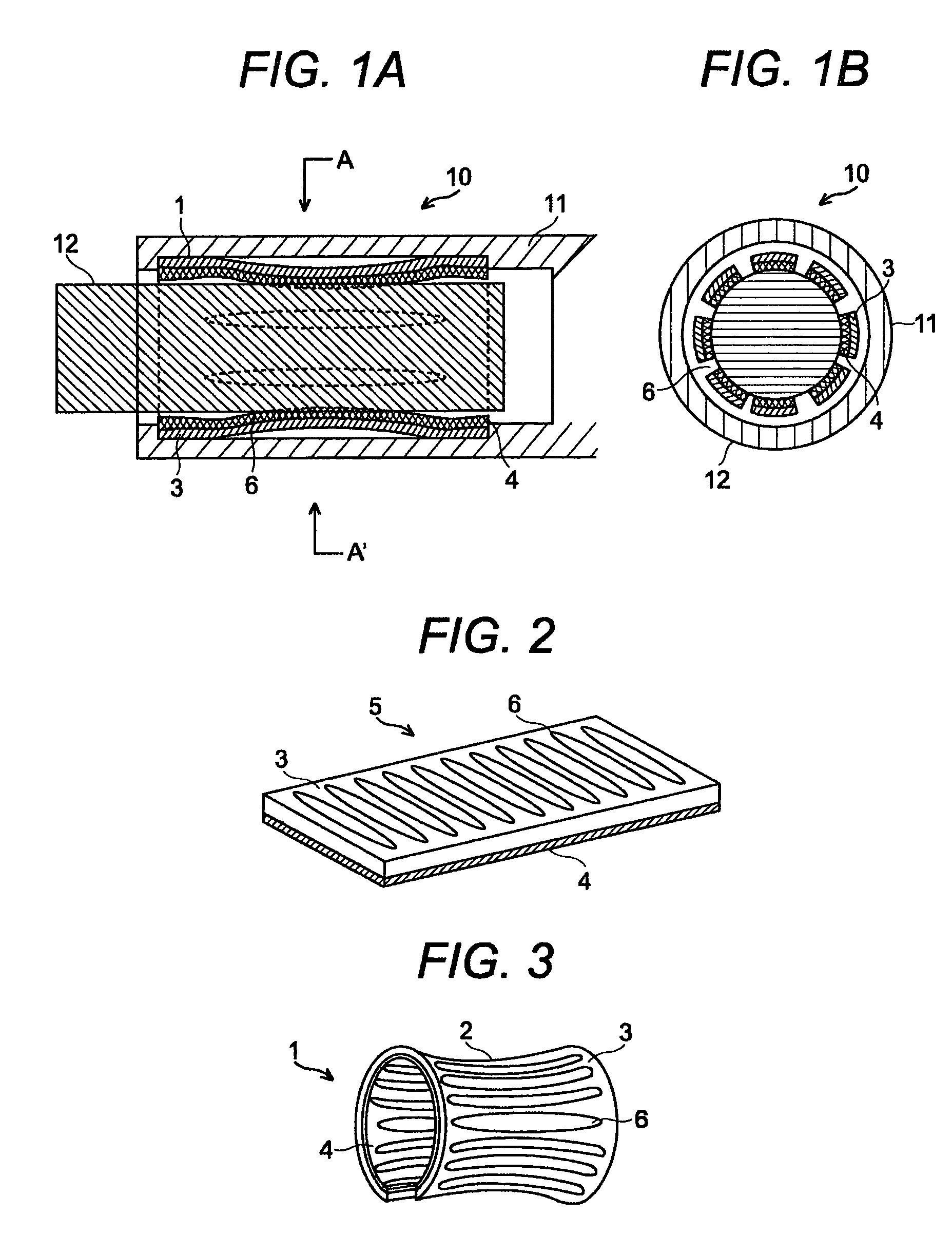
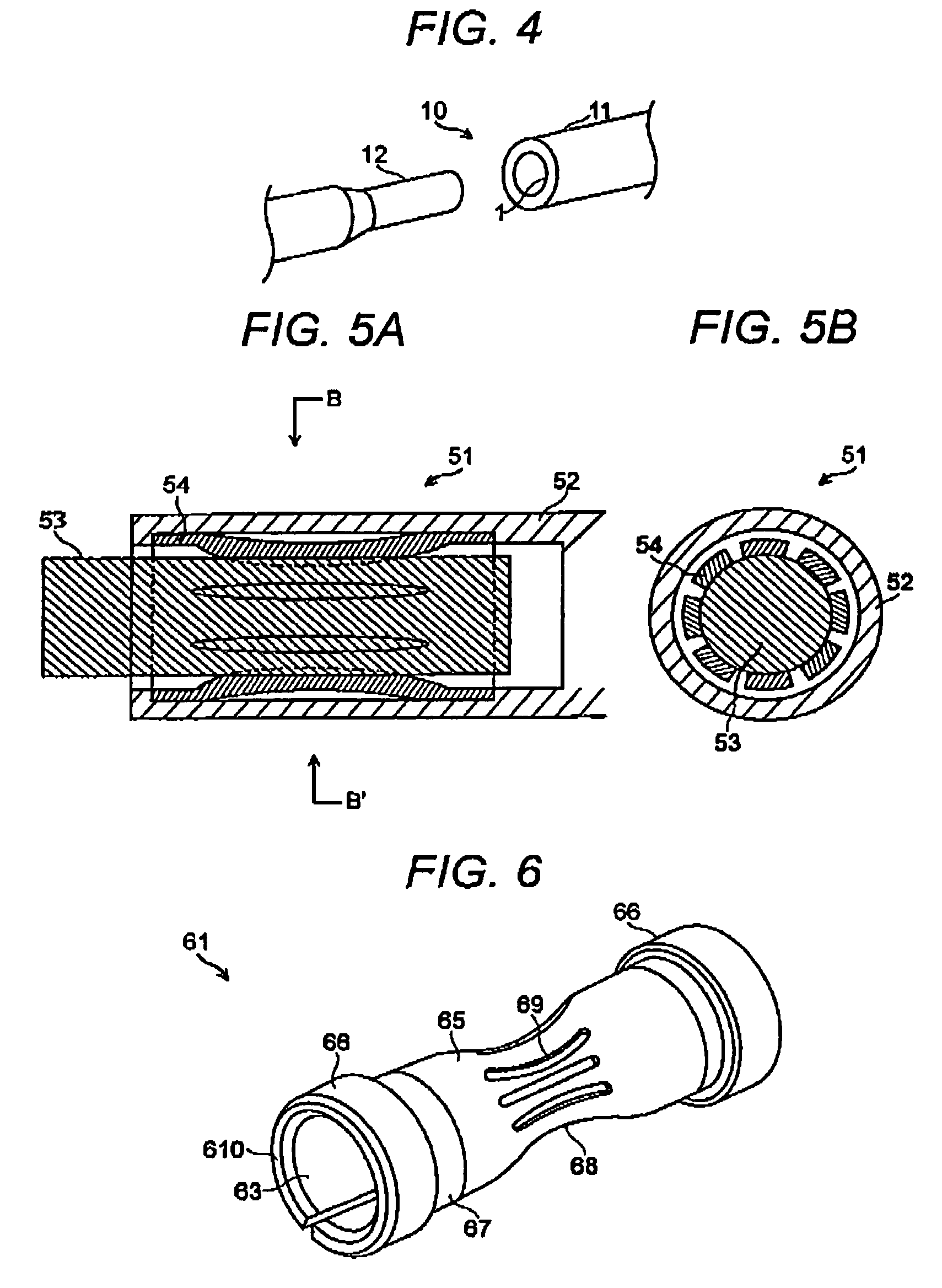
[0032]FIG. 1A is a section of the connector and FIG. 1B is a section taken along line A-A′ of FIG. 1A, both representing the best mode for embedding the present invention. FIG. 2 is a perspective view of the unfolded electric contact shown in FIG. 1A and FIG. 1B, FIG. 3 is a folded structure of the electric contact, and FIG. 4 is a perspective view of the connector shown in FIG. 1A and FIG. 1B.

[0033]As shown in FIGS. 1A, 1B, 3 and 4, the electric contact 1 used for connectors in this embodiment is formed in an approximately cylindrical shape and arranged inside the female contact maker formed in a cylindrical shape so as to accept the male contact maker 12 formed in a rod shape at the inside circumference of the electric contact in order to connect the electric wires together, in which the contact member 2 formed in an approximately cylindrical shape is formed with the composite m...


PUM


Abstract

An electric contact and a female terminal have high spring elasticity and high electric conductivity. In the electric contact 1 arranged inside the female contact maker 11, the contact member 2 in an approximately cylindrical shape is formed by the composite member composed of the electric conductive member 3 and the spring member 4.

Description

BACKGROUND OF THE INVENTION[0001]The present invention relates to an electric contact and a female terminal arranged inside the female contact maker in which the male contact maker is inserted.[0002]There is such an electric connector for carrying a high current over 100A that an electric connection is established between the female contact maker and the male contact maker by an electric contact having multiple contact makers configured as multiple springs shaped in a cylinder arranged inside the female contact maker.[0003]For example, a typical connector 51, as shown in FIG. 5A and FIG. 5B comprises a male contact maker 52, an electric contact 54. formed as a cylindrical shape and arranged inside the female contact maker 52, for accepting the male contact maker 52 inside itself. The electric contact 54 is used so that the electric contact 54 may be placed between the male contact maker 53 and the female contact maker 52. The conventional contact 54 is composed of a single material ...

Claims


Application Information

Patent Timeline
Patent Type & Authority Patents(United States)
IPC IPC(8): H01R13/33
CPCH01R13/187H01R13/111
Inventor TAKEHARA, HIDEAKICHIWATA, NAOFUMI
Owner HITACHI CABLE
Why Eureka
Try Eureka