Optical parametric amplifier
a parametric amplifier and optical technology, applied in the field of optical parametric amplifiers, can solve the problems of difficult to realize the exact state of sub>0/sub>=sub>p/sub>, and achieve the effect of high gain and broadband, and high gain for parametric amplification
- Summary
- Abstract
- Description
- Claims
- Application Information
AI Technical Summary
Benefits of technology
Problems solved by technology
Method used
Image
Examples
first embodiment
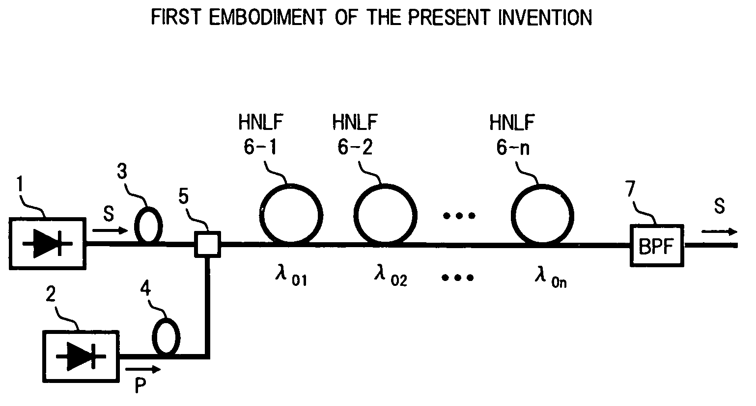
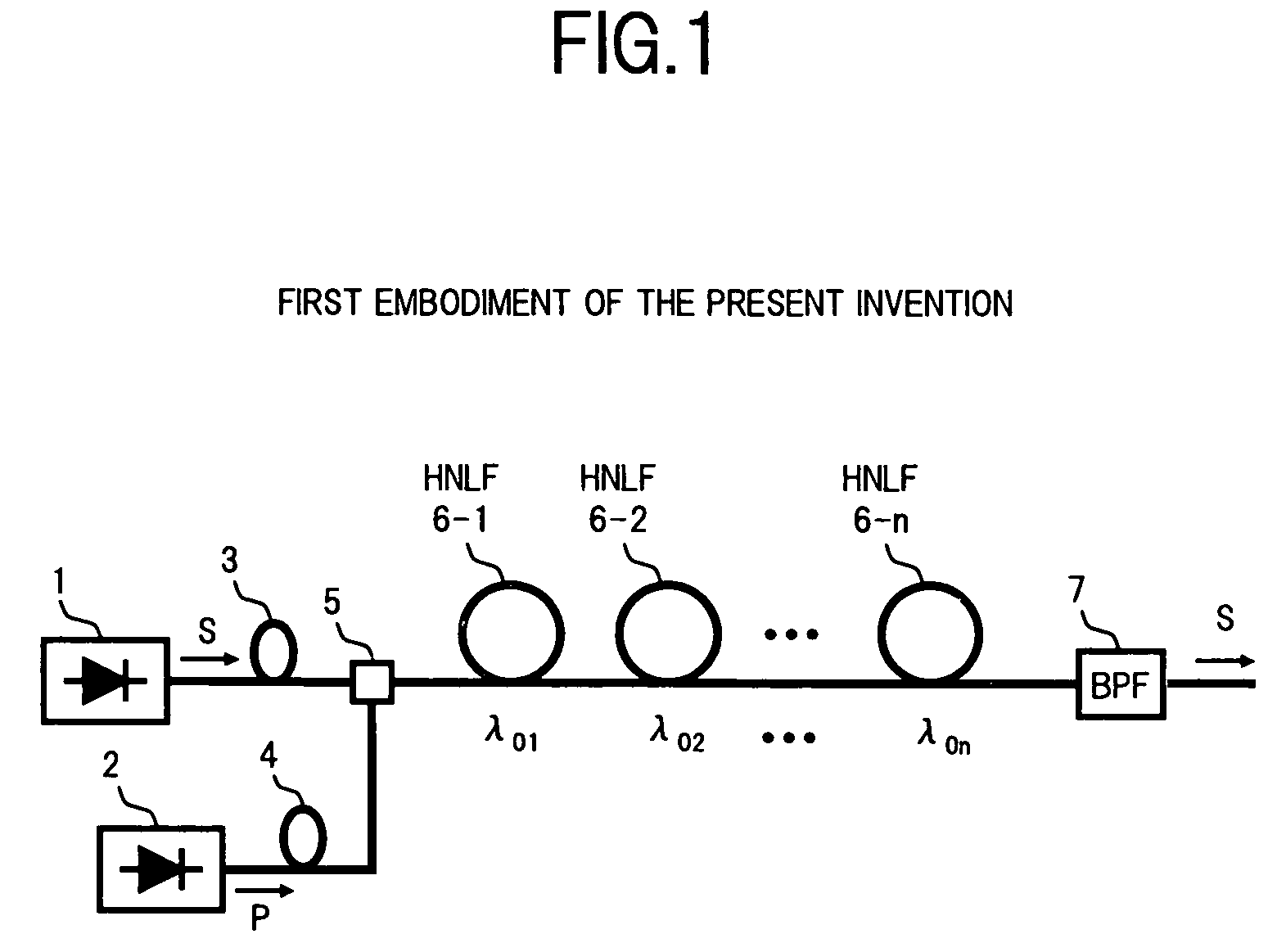
[0040]FIG. 1 is a diagram showing the structure of an optical parametric amplifier according to the present invention.
[0041]In FIG. 1, an optical parametric amplifier of the present embodiment comprises, for example: a signal light source 1 which generates a signal light S; a pump light source 2 which generates a pump light P; polarization controllers 3 and 4 serving as polarization control devices; a coupler 5 which combines the signal light S and the pump light P; n polarization retaining highly nonlinear optical fibers (hereunder referred to as HNLF) 6-1, 6-2, to 6-n, serving as a nonlinear amplifying section; and an optical bandpass filter 7 serving as a signal light extraction section.
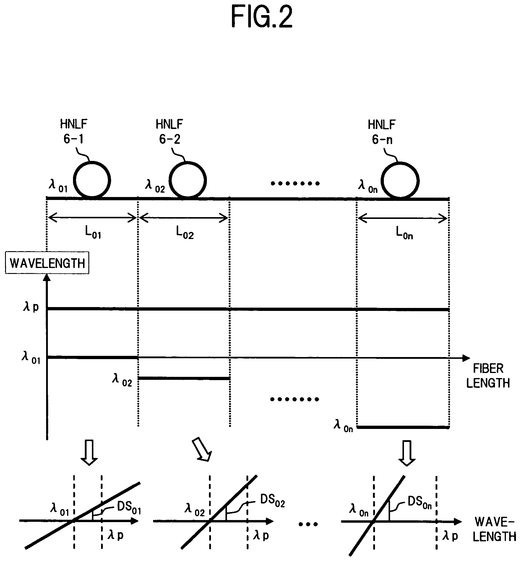
[0042]The signal light source 1 generates a signal light pulse S with a high-speed bit rate, in accordance with the OTDM system for example, and outputs the signal light S to the polarization controller 3. Here, an example is shown in which the signal light source 1 is provided in the optical para...
second embodiment
[0062]Next is a description of the present invention.
[0063]FIG. 6 is a diagram showing the structure of a second embodiment of an optical parametric amplifier according to the present invention.
[0064]In FIG. 6, an optical parametric amplifier of the present embodiment comprises n multi stage HNLFs 6-1 to 6-n, wherein m (16-1 to 6-m from among the n HNLFs 6-1 to 6-n in the structure of the first embodiment shown in FIG. 1 are connected in series, n-m HNLFs 6-m+1 to 6-n are connected in series, and the HNLFs 6-1 to 6-m and the HNLFs 6-m+1 to 6-n are connected in parallel by a coupler 8 and a coupler 9. The arrangement is set such that the zero-dispersion wavelengths λ0 to λ0m and λ0m+1 to λ0n of the HNLFs 6-1 to 6-m and 6-m+1 to 6-n become shorter towards the later stages of the HNLFs similarly to the case of the first embodiment, and there are relative relationships of λ01>λ02> . . . λ0m and λ0m+1>λ0m+2 . . . >λ0n. Furthermore, the arrangement is set such that the dispersion slopes D...
PUM
| Property | Measurement | Unit |
|---|---|---|
| zero-dispersion wavelengths | aaaaa | aaaaa |
| dispersion | aaaaa | aaaaa |
| dispersion slopes | aaaaa | aaaaa |
Abstract
Description
Claims
Application Information
 - R&D
- Intellectual Property
- Life Sciences
- Materials
- Tech Scout
- Unparalleled Data Quality
- Higher Quality Content
- 60% Fewer Hallucinations
Browse by: Latest US Patents, China's latest patents, Technical Efficacy Thesaurus, Application Domain, Technology Topic, Popular Technical Reports.
© 2025 PatSnap. All rights reserved.Legal|Privacy policy|Modern Slavery Act Transparency Statement|Sitemap|About US| Contact US: help@patsnap.com


