
Optical parametric amplifier

Inactive Publication Date: 2007-09-06
FUJITSU LTD
View PDF2 Cites 2 Cited by
  • Summary
  • Abstract
  • Description
  • Claims
  • Application Information

AI Technical Summary

Benefits of technology

[0023] The present invention addresses the above-described points, with an object of providing an optical parametric amplifier that can realize high gain and broadband using a simple structure. Furthermore, an object is to provide an optical parametric amplifier that can amplify a signal light of a desired wavelength by high parametric gain.
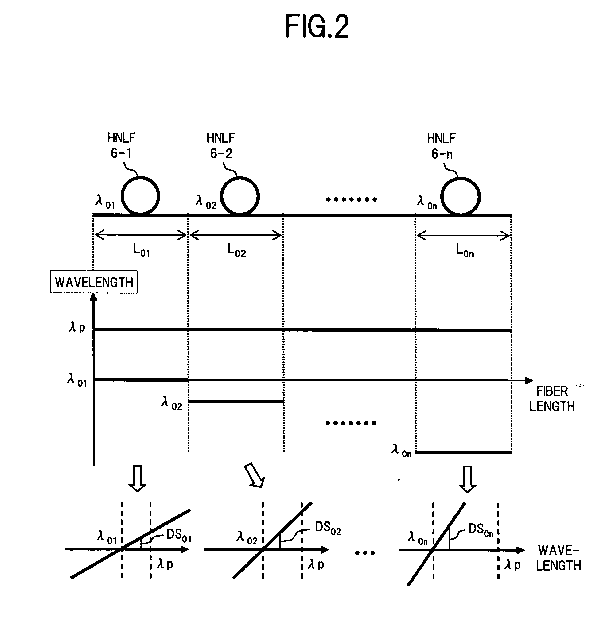
[0025] Regarding the plurality of nonlinear amplification media of the optical parametric amplifier, it is preferable that each of their zero-dispersion wavelengths is on the short wavelength side from a wavelength of the pump light, and the zero-dispersion wavelengths of nonlinear amplification media that are relatively located on the signal light input side are on the long wavelength side from the zero-dispersion wavelengths of nonlinear amplification media that are relatively located on the signal light output side. Furthermore, it is desirable that dispersion slopes of nonlinear amplification media that are relatively located on the signal light output side are steeper than dispersion slopes of nonlinear amplification media that are relatively located on the signal light input side. Moreover, it is desirable to have high nonlinearity in which a range over which nonlinear optical effects can be obtained effectively is narrower than a range over which group velocity dispersion occurs. By using a plurality of nonlinear amplification media as described above, it is possible to obtain high parametric gain over a broad band from the vicinity of the pump light wavelength.
[0027] According to the parametric amplifier of the present invention as described above, even in the case where the zero-dispersion wavelength of the nonlinear amplification medium does not coincide with the pump light wavelength, by optimizing the zero-dispersion wavelengths of the multi-stage nonlinear amplification media, and the dispersion slopes, it is possible to realize high gain and broadband for parametric amplification. Furthermore, it is possible to achieve high gain for parametric amplification without causing structural complexity, by designing the dispersion slopes of the nonlinear amplification media in consideration of the desired signal light wavelengths.

Problems solved by technology

On the other hand, in recent years, attention has been given to optical time division multiplexing (OTDM) transmission systems, in which the bit rate per wavelength is increased and signal lights are multiplexed by time division, due to problems such as the increase in power consumption caused by increasing numbers of wavelengths.
Incidentally, as is apparent from the fact that the above-described conventional optical amplifiers realize broadband by combining cascading Raman amplification and parametric amplification or four wave mixing, regarding an optical parametric amplifier that amplifies a signal light parametrically, there is a problem in that it is difficult to realize the desired bandwidth and gain in the case where a signal light is amplified using parametric amplification on its own.
However, since the zero-dispersion wavelength λ0 of the nonlinear fiber actually used cannot avoid fluctuation in the longitudinal direction, it is difficult to realize the state of λ0=λp exactly.
However, this is not easy to realize due to the aforementioned fluctuations and the like of the zero-dispersion wavelength λ0.
When the dispersion slope is zero (dDc / dλ=0), the relationship of equation (2) is not satisfied, and hence phase mismatching always remains, causing a decrease in the gain.
However, since an optical parametric amplifier using two wavelength excitation requires literally two pump light sources, there is a problem in that it has a cost disadvantage.

Method used


Image

  • Optical parametric amplifier
  • Optical parametric amplifier
  • Optical parametric amplifier

Examples


first embodiment

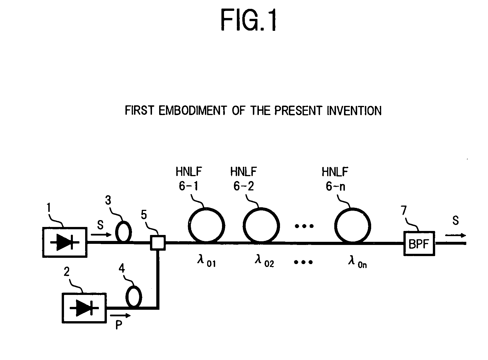
[0038]FIG. 1 is a diagram showing the structure of an optical parametric amplifier according to the present invention.

[0039] In FIG. 1, an optical parametric amplifier of the present embodiment comprises, for example: a signal light source 1 which generates a signal light S; a pump light source 2 which generates a pump light P; polarization controllers 3 and 4 serving as polarization control devices; a coupler 5 which combines the signal light S and the pump light P; n polarization retaining highly nonlinear optical fibers (hereunder referred to as HNLF) 6-1, 6-2, to 6-n, serving as a nonlinear amplifying section; and an optical bandpass filter 7 serving as a signal light extraction section.

[0040] The signal light source 1 generates a signal light pulse S with a high-speed bit rate, in accordance with the OTDM system for example, and outputs the signal light S to the polarization controller 3. Here, an example is shown in which the signal light source 1 is provided in the optical p...

second embodiment

[0060] Next is a description of the present invention.

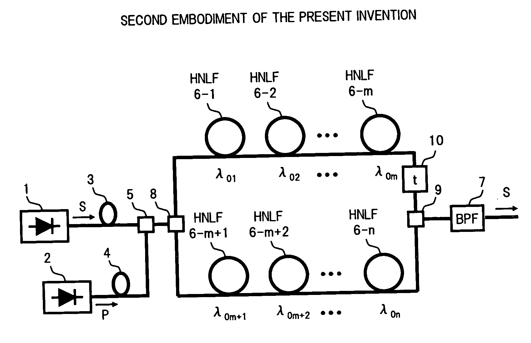
[0061]FIG. 6 is a diagram showing the structure of a second embodiment of an optical parametric amplifier according to the present invention.

[0062] In FIG. 6, an optical parametric amplifier of the present embodiment comprises n multi stage HNLFs 6-1 to 6-n, wherein m (16-1 to 6-m from among the n HNLFs 6-1 to 6-n in the structure of the first embodiment shown in FIG. 1 are connected in series, n-m HNLFs 6-m+1 to 6-n are connected in series, and the HNLFs 6-1 to 6-m and the HNLFs 6-m+1 to 6-n are connected in parallel by a coupler 8 and a coupler 9. The arrangement is set such that the zero-dispersion wavelengths λ0 to λ0m and λ0m+1 to λ0n of the HNLFs 6-1 to 6-m and 6-m+1 to 6-n become shorter towards the later stages of the HNLFs similarly to the case of the first embodiment, and there are relative relationships of λ01>λ02> . . . λ0m and λ0m+1>λ0m+2 . . . >λ0n. Furthermore, the arrangement is set such that the dispersion slope...


PUM


Abstract

An optical parametric amplifier of the invention comprises a nonlinear amplification section to which a signal light and a pump light are injected via a coupler. The nonlinear amplification section is constructed by connecting in multiple stages a plurality of polarization retaining highly nonlinear optical fibers (HNLFs) having mutually different zero-dispersion wavelengths and dispersion slopes. The zero-dispersion wavelengths of the HNLFs are on the short wavelength side of a pump light wavelength, and are shorter towards the output side HNLF. Furthermore, the arrangement is set such that the dispersion slopes of the HNLFs become steeper towards the output side HNLF. As a result, it is possible to realize an optical parametric amplifier that is high gain and broadband.

Description

BACKGROUND OF THE INVENTION [0001] 1. Field of the Invention [0002] The present invention relates to an optical parametric amplifier which amplifies a signal light parametrically using nonlinear optical effects. In particular, it relates to a technique designed for high gain and broadband parametric amplification. [0003] 2. Description of the Related Art [0004] Currently, optical wavelength division multiplexing (WDM) transmission systems, in which a plurality of signal lights with different wavelengths is multiplexed for transmission by one optical fiber, are coming into practical use. On the other hand, in recent years, attention has been given to optical time division multiplexing (OTDM) transmission systems, in which the bit rate per wavelength is increased and signal lights are multiplexed by time division, due to problems such as the increase in power consumption caused by increasing numbers of wavelengths. [0005] In the OTDM transmission system, since the bit rate is high, an...

Claims


Application Information

Patent Timeline
IPC IPC(8): G02F1/35
CPCG02F1/395G02F2201/16G02F2001/392G02F1/392
Inventor ONO, SHUNSUKEWATANABE, SHIGEKI
Owner FUJITSU LTD
Learn More