Measuring method and device for liquid crystal viscosity coefficient

a technology of viscosity coefficient and measuring method, which is applied in the direction of measurement devices, scientific instruments, instruments, etc., can solve the problems of insufficient accuracy, long calculation time, and low accuracy, and achieve the effect of reducing the time required for calculation and improving the accuracy of measuremen

Inactive Publication Date: 2008-06-24
TOHOKU TECHNO BRAINS +1
View PDF6 Cites 3 Cited by
  • Summary
  • Abstract
  • Description
  • Claims
  • Application Information

AI Technical Summary

Benefits of technology

[0024]In the present invention, using electro-optical response characteristics that are less subject to other viscosity coefficients, the 1st fitting for the rotational viscosity coefficient is initially performed, and the 2nd fitting for the shear viscosity coefficients is subsequently performed. This not only greatly improves the accuracy of measurement, but also significantly reduces the time required for calculation, because the number of parameters simultaneously varied is only two at a maximum.

Problems solved by technology

However, the conventional measurement by fitting described above has problems in that it requires as much as four parameters simultaneously varied, takes a long time to calculate, and is low in accuracy.
Moreover, the measuring method using a rotational viscometer can measure only the rotational viscosity coefficient γ1, and its accuracy is insufficient.
That is, in the conventional art, there is no established method for measuring the above-described five viscosity coefficients that are dominant factors in determining the LCD response.

Method used


Image

  • Measuring method and device for liquid crystal viscosity coefficient
  • Measuring method and device for liquid crystal viscosity coefficient
  • Measuring method and device for liquid crystal viscosity coefficient

Examples


example

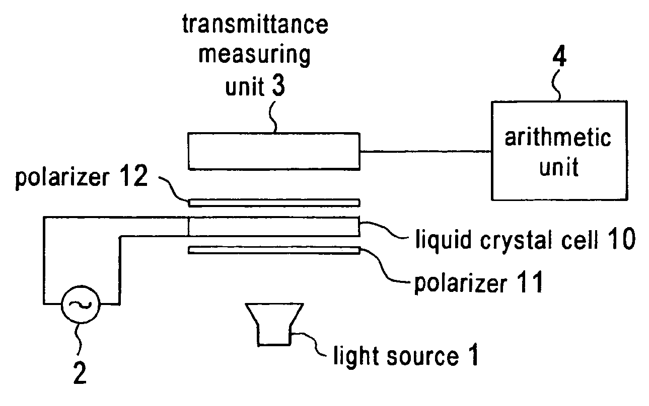
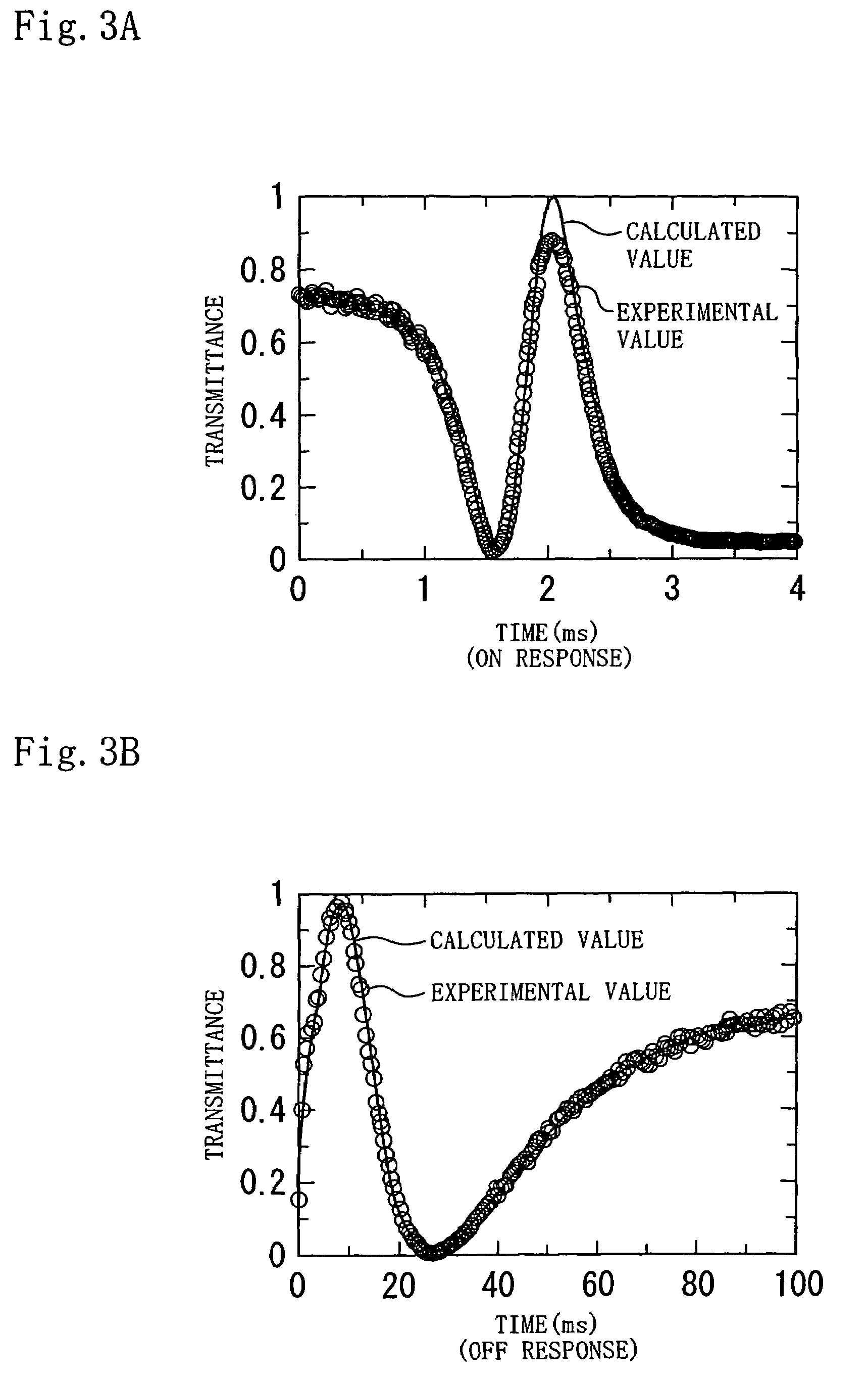
[0051]A liquid crystal material TD1016XX (produced by Chisso Corporation), an alignment layer AL1254 (produced by Japan Synthetic Rubber Company Limited) are used to produce a liquid crystal cell (cell gap: 6 μm) with homogeneous alignment, thereby measuring the response characteristics according to the measuring method of the present invention. A measuring device having a structure as shown in FIG. 2 is used. The applied voltage is an alternating voltage of a square wave with a period of 1 ms and an amplitude of 10 V at a higher level, and is a constant voltage 0 V at a lower level. FIG. 3A and FIG. 3B show the result obtained by fitting the experimental values and the calculated values in the first step (ON response: FIG. 3A) and the second step (OFF response: FIG. 3B). The viscosity coefficients determined by the fitting are γ1=131 cP, η1=145 cP, and η2=12 cP, where 1 cP (centipoise)=1 mPa·s.

[0052]To test the reliability of the values determined, a liquid crystal cell with bend a...


PUM

PropertyMeasurementUnit
tilt anglesaaaaaaaaaa
azimuth angleaaaaaaaaaa

Abstract

In a measuring method for determining values of viscosity coefficients of a liquid crystal by fitting Ericksen-Leslie theoretical values to measured response characteristics, in the first step, ON response characteristics of a liquid crystal cell 10 with homogeneous alignment are initially measured, and a value of a rotational viscosity coefficient γ1 is determined from the measured ON response characteristics. Then, in the second step, OFF response characteristics are measured, and values of Miesovicz shear viscosity coefficients η1 and η2 are determined from the measured OFF response characteristics. In the calculation in the first step, the viscosity coefficients other than γ1 are assigned general values. In the calculation in the second step, γ1 is assigned the value determined in the first step.

Description

TECHNICAL FIELD[0001]The present invention relates to methods and devices for measuring viscosity coefficients of a liquid crystal, and specifically to a method and device capable of measuring a rotational viscosity coefficient γ1, and η1 and η2 of Miesovicz viscosity coefficients of a liquid crystal, with a high degree of accuracy.BACKGROUND ART[0002]With recent advances in liquid crystal televisions, there are strong demands for the development of liquid crystal displays (hereinafter may be simply referred to as “LCDs”) capable of performing higher-speed switching. The present inventors have revealed that a flow effect of liquid crystal plays an important role in the LCD response (S. Onda, T. Miyashita, T. Uchida: Asia Display 98 Proceedings (1998) p. 1055). The theory of flow effect was developed by Ericksen-Leslie (F. M. Leslie: Quart. J. Mech, Appl. Math., 19 (1966) p. 357; F. M. Leslie: Liquid Crystals (1968) p. 365; and J. L. Ericksen: Mol. Cryst. Liq. Cryst. (1969) p. 153). ...

Claims


Application Information

Patent Timeline
Patent Type & Authority Patents(United States)
IPC IPC(8): G01N11/00C09K19/02G01N21/59G02F1/00
CPCC09K19/02G01N11/00G02F1/0072G01N2011/0066G01N2011/0073G01N21/59
Inventor UCHIDA, TATSUOMIYASHITA, TETSUYAISHINABE, TAKAHIRO
Owner TOHOKU TECHNO BRAINS
Why Eureka
Try Eureka