Pump-bottle atomizer

a technology of atomizer and pump mechanism, which is applied in the direction of instruments, pliable tubular containers, single-unit apparatuses, etc., can solve the problems of unavoidable patient cross-contamination, unfavorable patient safety, and inability to fit in the custom support apparatus ubiquitous in the therapy room, etc., to maintain the sterility of the atomizer, low cost, and low cos

Active Publication Date: 2008-06-24
TELEFLEX MEDICAL INC
View PDF34 Cites 13 Cited by
  • Summary
  • Abstract
  • Description
  • Claims
  • Application Information

AI Technical Summary

Benefits of technology

[0009]A pump mechanism used in the instant invention typically includes a pump head that can be displaced by a human digit through a vertical distance between a first and a second elevation. One desirable brace, generally useful in atomizers according to the invention, can be configured and arranged to hold the conduit to provide a fulcrum location at a third elevation, with the third elevation being approximately midway between the first and the second elevations, thus reducing a horizontal displacement of the fulcrum during vertical actuation of the pump mechanism. It is also within contemplation that a proximal portion of the conduit, located between the pump head and structure carried at the second end of the brace, can be configured and arranged to reduce a horizontal deflection of the nozzle during actuation of said pump mechanism.
[0011]Exemplary braces are adapted for removable attachment to the conduit. Furthermore, the pump head is desirably adapted for removable attachment to the pump mechanism, thus permitting replacement of a low cost assembly comprising the pump head, the conduit, and the atomizing nozzle. The low cost assembly may be replaced between treatment of different patients to maintain sterility of the atomizer and prevent patient cross-contamination.

Problems solved by technology

A concern in use of such atomizers is the possibility for unavoidable patient cross-contamination.
Positive pressure pump-bottle atomizers may prevent patient cross-contamination, but generally do not fit in the custom support apparatus ubiquitous in therapy rooms.
Furthermore, operation of the pump mechanism can undesirably alter the point of impact of a discharge mist.
Therefore, while attempting to treat a nostril, a therapist may accidentally squirt a patient in the eye, or cheek.
In any event, when delivery of the treatment fluid is not well controlled, an over- or under-medicated state may occur in the patient.
Consequently, manipulation of a direction of discharge from the nozzle may be limited.
However, such an atomizer still lacks a desirably stable atomizer nozzle for control of the discharge impact site.

Method used


Image

  • Pump-bottle atomizer
  • Pump-bottle atomizer
  • Pump-bottle atomizer

Examples


Embodiment Construction

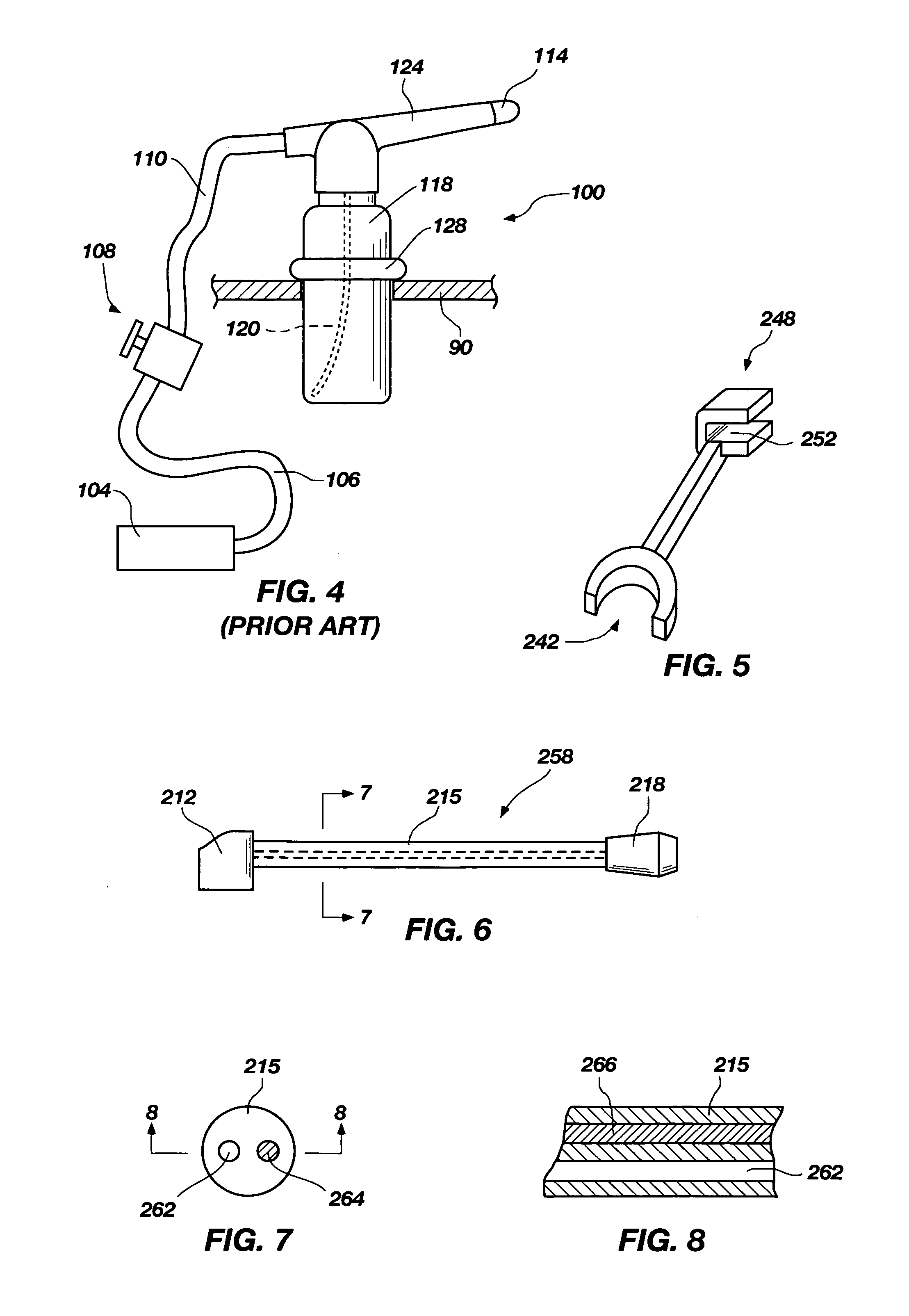
[0022]A widely used, venturi-type atomizer, generally indicated at 100, is illustrated in FIG. 4. Atomizer 100 is known as a DeVilbiss atomizer, and is sold by Sunrise Medical HHG Inc., of Somerset, Pa. U.S.A. A DEVILBISS atomizer 100 typically requires a pressurized air source 104, connecting tubing 106, a valve 108, and more tubing 110. In use, a practitioner causes a fluid discharge from nozzle tip 114 by opening valve 108. Fluid contained in bottle 118 is drawn through suction line 120, passes along extended nozzle 124, and finally exits in misted form at tip 114.

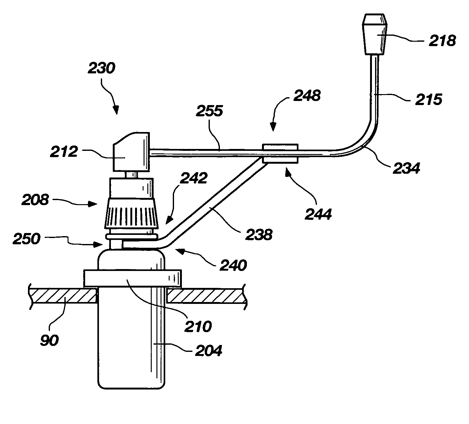
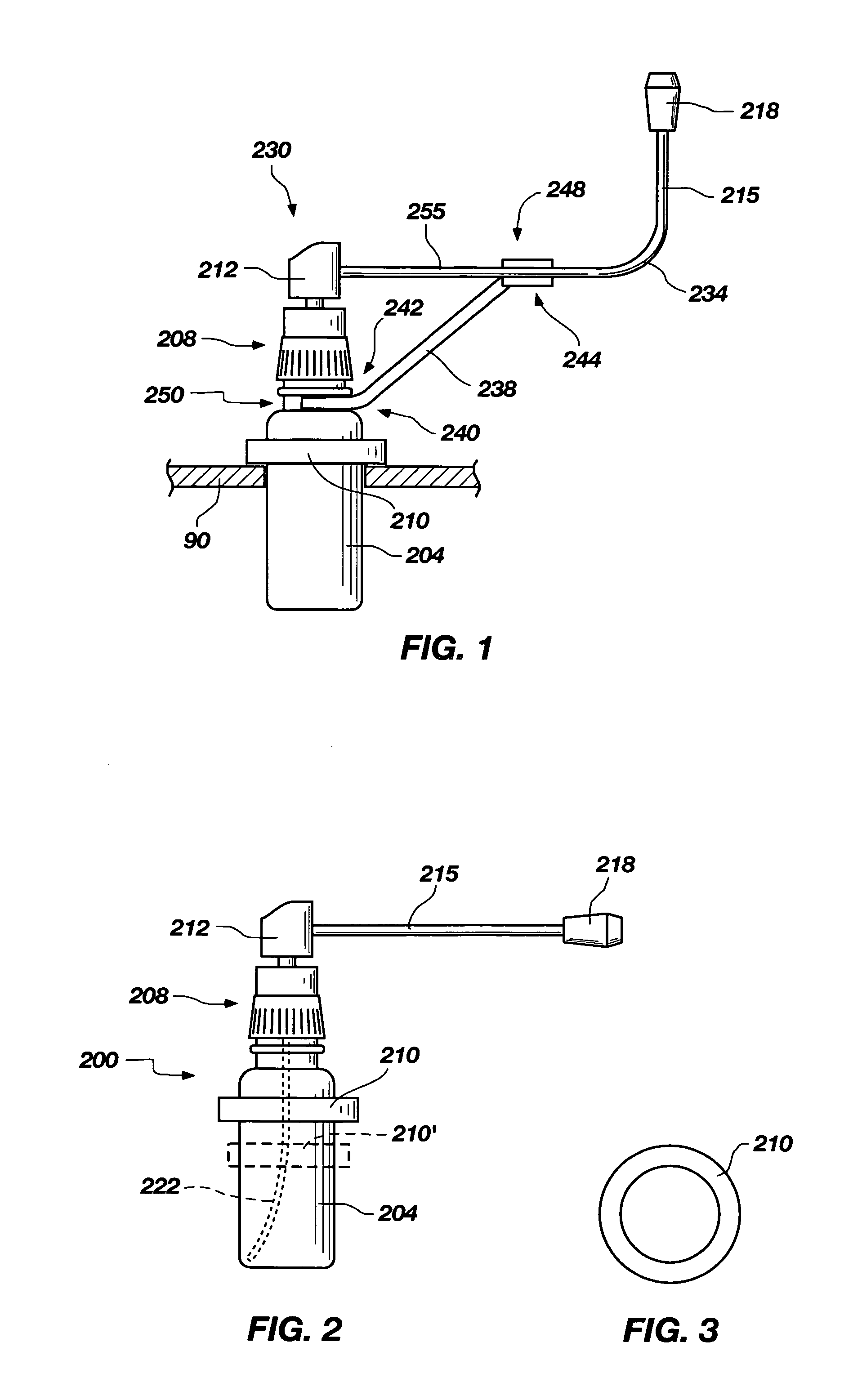
[0023]Atomizers constructed according to atomizer 100 and illustrated in FIG. 4 have been long and widely used, and have spawned custom support apparatus constructed in correspondence with characteristics of bottle 118. One typical receiving structure 90 for an atomizer 100 provides a hole with a diameter sized to receive the bottom end of bottle 118. An enlarged portion of bottle 118 forms a bottle support 128 operable...


PUM


Abstract

A fluid atomizer that can include an orientable extension conduit between a pump bottle and an atomizing nozzle. A brace element between the bottle and the conduit limits movement of the nozzle during actuation of the pump mechanism. A resilient enlargement to engage the bottle may be included to permit suspending the bottle in commercially available storage racks.

Description

TECHNICAL FIELD[0001]The invention relates to atomizing nozzles and devices which dispense fluids in a misted form. Certain devices constructed according to the instant invention are particularly suitable for use in nasal and oral medication therapy. One aspect of the invention resolves a bottle suspension problem.BACKGROUND[0002]A long and widely used atomizer is known as a “DeVilbiss atomizer”. The DeVilbiss atomizer uses the Venturi principle to extract fluids from a reservoir for subsequent discharge through a nozzle as a mist. Such atomizers have support apparatus custom formed to accommodate a certain bottle shape. A concern in use of such atomizers is the possibility for unavoidable patient cross-contamination.[0003]Positive pressure pump-bottle atomizers may prevent patient cross-contamination, but generally do not fit in the custom support apparatus ubiquitous in therapy rooms. Furthermore, operation of the pump mechanism can undesirably alter the point of impact of a disch...

Claims


Application Information

Patent Timeline
Patent Type & Authority Patents(United States)
IPC IPC(8): B05B9/043A61M11/02A62C11/00B05B11/00
CPCA61M11/02B05B11/0089B05B11/30Y10S239/12B05B11/10
Inventor DENTON, MARSHALL T.
Owner TELEFLEX MEDICAL INC
Why Eureka
Try Eureka