
Tube connection assembly of bicycle frame

a technology of bicycle frame and tube connection, which is applied in the direction of friction roller based transmission, steering device, cycle equipment, etc., can solve the problems of easy mechanical fatigue, prolonged time, and damage to the structure, and achieves the effect of increasing the strength of the bicycle frame, and reducing the number of tubes

Inactive Publication Date: 2008-06-24
IDEAL BIKE CORP
View PDF6 Cites 5 Cited by
  • Summary
  • Abstract
  • Description
  • Claims
  • Application Information

AI Technical Summary

Benefits of technology

The solution increases the connection area, reducing mechanical fatigue and prolonging the bicycle frame's lifespan by dispersing loads evenly, while simplifying the manufacturing process and reducing costs.

Problems solved by technology

Thereby it is easy to have mechanical fatigue if the bicycle moves on uneven paths.
Furthermore, the structure is destroyed.
However this prior art needs a multi-stub tube so that the many aluminum extrusion and cutting processes are necessary.
Thus, the time is prolonged and cost is increased.
By a tube with at least two hollow areas, this induces many confinements and inconveniences.

Method used


Image

  • Tube connection assembly of bicycle frame
  • Tube connection assembly of bicycle frame
  • Tube connection assembly of bicycle frame

Examples


Embodiment Construction

[0012]In order that those skilled in the art can further understand the present invention, a description will be provided in the following in details. However, these descriptions and the appended drawings are only used to cause those skilled in the art to understand the objects, features, and characteristics of the present invention, but not to be used to confine the scope and spirit of the present invention defined in the appended claims.

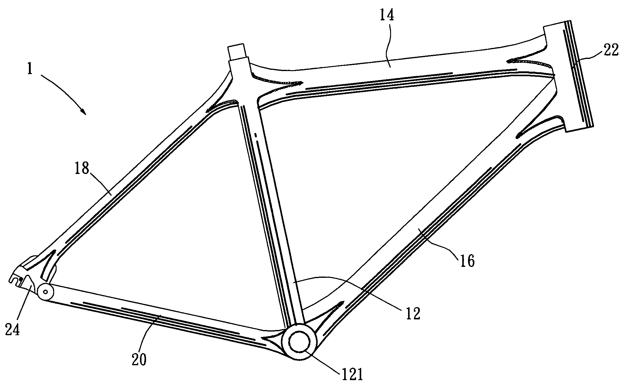
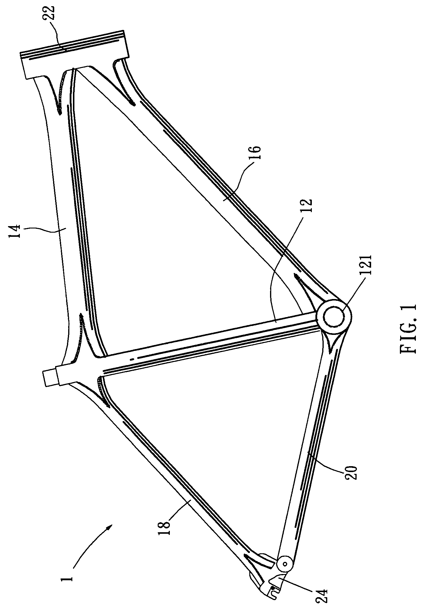
[0013]The present invention related to a tube connection assembly of a bicycle frame. As shown in FIG. 1, in generally, the bicycle frame has the following elements. A stand tube 12 has a top. A front end of the stand tube 12 is combined with an upper tube 14 and a rear end thereof is combined with a rear upper bi-forked tube 18. A five-stub tube 121 is installed at a bottom end of the stand tube 12. A front end of the five-stub tube 121 has a lower tube 16 and a rear end thereof has a rear lower bi-forked tube 20. The upper tube 14 and lower tube ...


PUM


Abstract

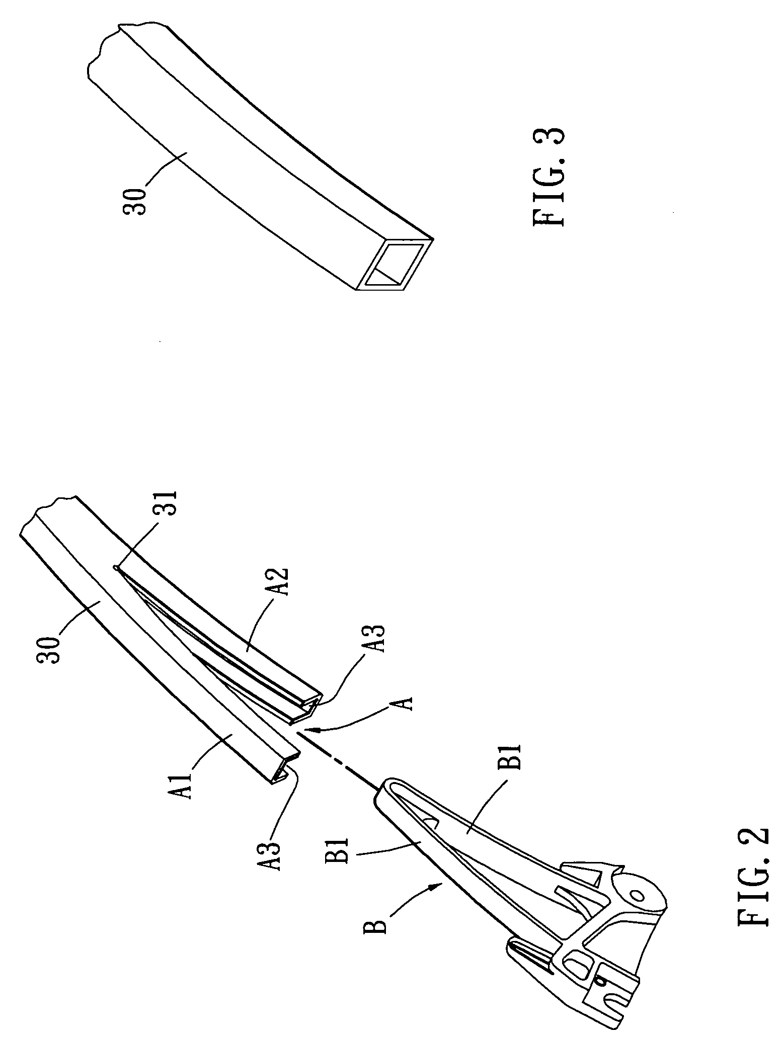
A tube connection assembly of a bicycle frame includes a bi-forked portion formed by a hollow rectangular tube; one end of the rectangular tube being bi-forked as two halves; each half having a positioning groove; and a combining portion formed by two plates which are connected as a shape corresponding to that of the positioning groove and the bi-forked portion so that in assembly the combining portion is assembled to the bi-forked portion; and connection area of the bi-forked portion and combining portion being welded.

Description

FIELD OF THE INVENTION[0001]The present invention relates to bicycle frames, and in particular to a tube connection assembly of a bicycle frame, wherein the present invention provides a greater combing area between tubes, thus the strength of the bicycle frame is increased so that it can bear a heavier load. The load can be dispersed to the whole area of the connection so that the mechanical fatigue is reduced and the lifetime of the bicycle frame is prolonged.BACKGROUND OF THE INVENTION[0002]Conventionally, in the assembly of a bicycle frame, as illustrated in Taiwan Patent No. 584123, a bicycle frame of a bicycle, end portions of the transversal upper tube, lower tube, or rear bi-forked tube resist against and welded to a cambered surface of a longitudinal tube. Thereby the tubes are formed as a bicycle frame.[0003]In above bicycle frame, the connection area is small so that the welding area cannot suffer from a heavy load. Thereby it is easy to have mechanical fatigue if the bicy...

Claims


Application Information

Patent Timeline
Patent Type & Authority Patents(United States)
IPC IPC(8): B62K3/02B62K19/00
CPCB62K19/06B62K19/18B62K19/28
Inventor LIN, CHUN-HUNG
Owner IDEAL BIKE CORP
Learn More