Electronic signal processor

a signal processor and electronic technology, applied in the field of electronic signal processors, can solve the problems of increasing the amount of distortion present in the processor output, contributing to the distortion characteristics of the signal processor, and the output amplitude of the amplifier, so as to improve the ability to alter the tonal characteristics of the audio frequency input signal and reduce the distortion of the lower frequency intermodulation

Inactive Publication Date: 2008-06-24
ARNOLD JEFFREY
View PDF26 Cites 30 Cited by
  • Summary
  • Abstract
  • Description
  • Claims
  • Application Information

AI Technical Summary

Benefits of technology

[0016]This invention is directed to an electronic signal processor that has improved ability to alter the tonal characteristics of an audio frequency input signal and to reduce lower frequency intermodulation distortion. The signal processor may have a buffer stage to receive the input signal and to provide an input signal with low output impedance to the first filter of the signal processor.
[0017]A first filter is preferably a second or third order high pass filter with a frequency response curve of 12 db / octave slope or 18 db / octave slope for the lower frequencies, respectively. One of the purposes of the first filter is to substantially reduce lower frequency intermodulation distortion by means of such filtering. The first filter also has at least some user-selectable corner frequencies in its frequency response curve so that the user may customize the tonal quality of the signal processor. The first filter preferably also includes at least two adjustable gain levels with overlapping gain characteristics that may be pre-set by the user and that may be alternately selected. The multiple, user-preset, selectable gain levels allow the user to adjust the amount of distortion present in, and therefore the tonal color of, the processor output.
[0018]The output of the first filter is input to one or more limiting gain stages, which are in series or cascade configuration. These gain stages can increase the amount of distortion present in the processor output. Oppositely poled diodes in the feedback circuits of the amplifiers in the gain stages limit the output amplitude of the amplifiers and contribute to the distortion characteristics of the signal processor. Preferably, the gain stages have an additional or second feedback circuit that introduces a controlled amount of hysteresis, a nonlinear distortion, in the amplification characteristic of the gain stages. Thus, when the gain stages are overdriven by the input signal, the clipping or distortion in the output signal of the gain stages will be enhanced.
[0019]The present invention also relates to amplifiers with two feedback loops for use in the gain stages of signal processors. The first feedback loop includes a resistor, a capacitor and at least two diodes, with the diodes oppositely poled between the output of the amplifier and its inverting input. The second feedback circuit includes at least one resistor and at least one capacitor coupled between the output of the amplifier and the input of the gain stage. A resistor preferably couples the second feedback loop to the inverting input of the amplifier. The two feedback loops interact to enhance the distortion when the amplifier is overdriven by an input signal.

Problems solved by technology

These gain stages can increase the amount of distortion present in the processor output.
Oppositely poled diodes in the feedback circuits of the amplifiers in the gain stages limit the output amplitude of the amplifiers and contribute to the distortion characteristics of the signal processor.

Method used


Image

  • Electronic signal processor
  • Electronic signal processor
  • Electronic signal processor

Examples


Embodiment Construction

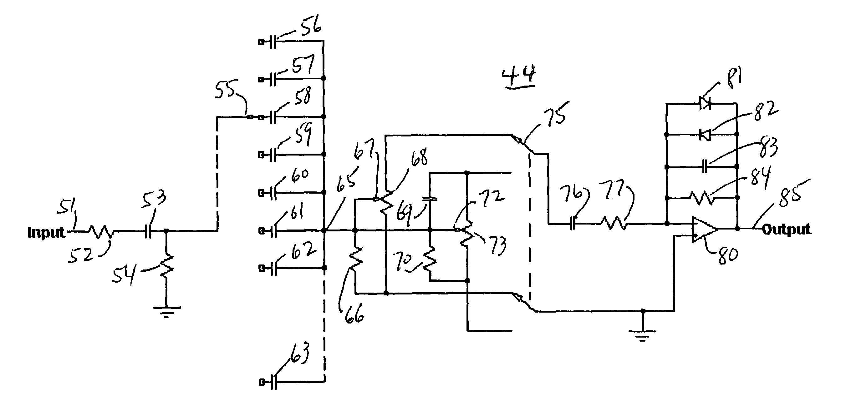
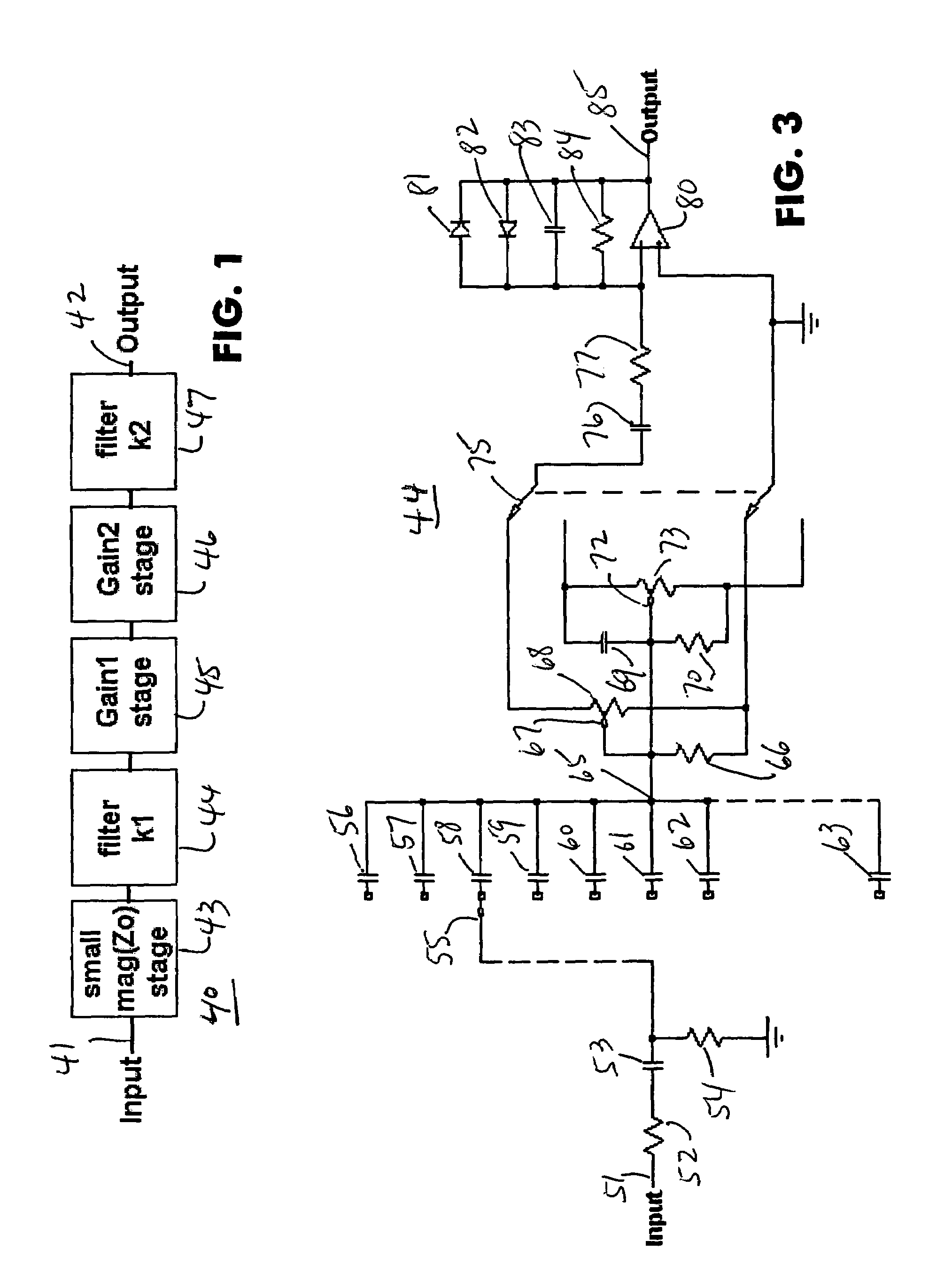
[0038]The present invention of a signal processing circuit, generally designated 40, is shown in block diagram format in FIG. 1. An input signal is received at an input terminal 41 to a small magnitude output impedance stage 43. Stage 43 preferably has an output impedance that is significantly smaller than the input impedance of a first filter k144 so as not to materially affect the corner frequencies of the first filter 44. First filter 44 is a complex filter with multiple user-adjustable corner frequencies and passband gains. The output of filter 44 is input into a first gain stage 45. The output of the first gain stage 45 is input into a second gain stage 46. The output of the second gain stage 46 is input into a second filter k247, which provides the output signal of the signal processing circuit 40 at a terminal 42.

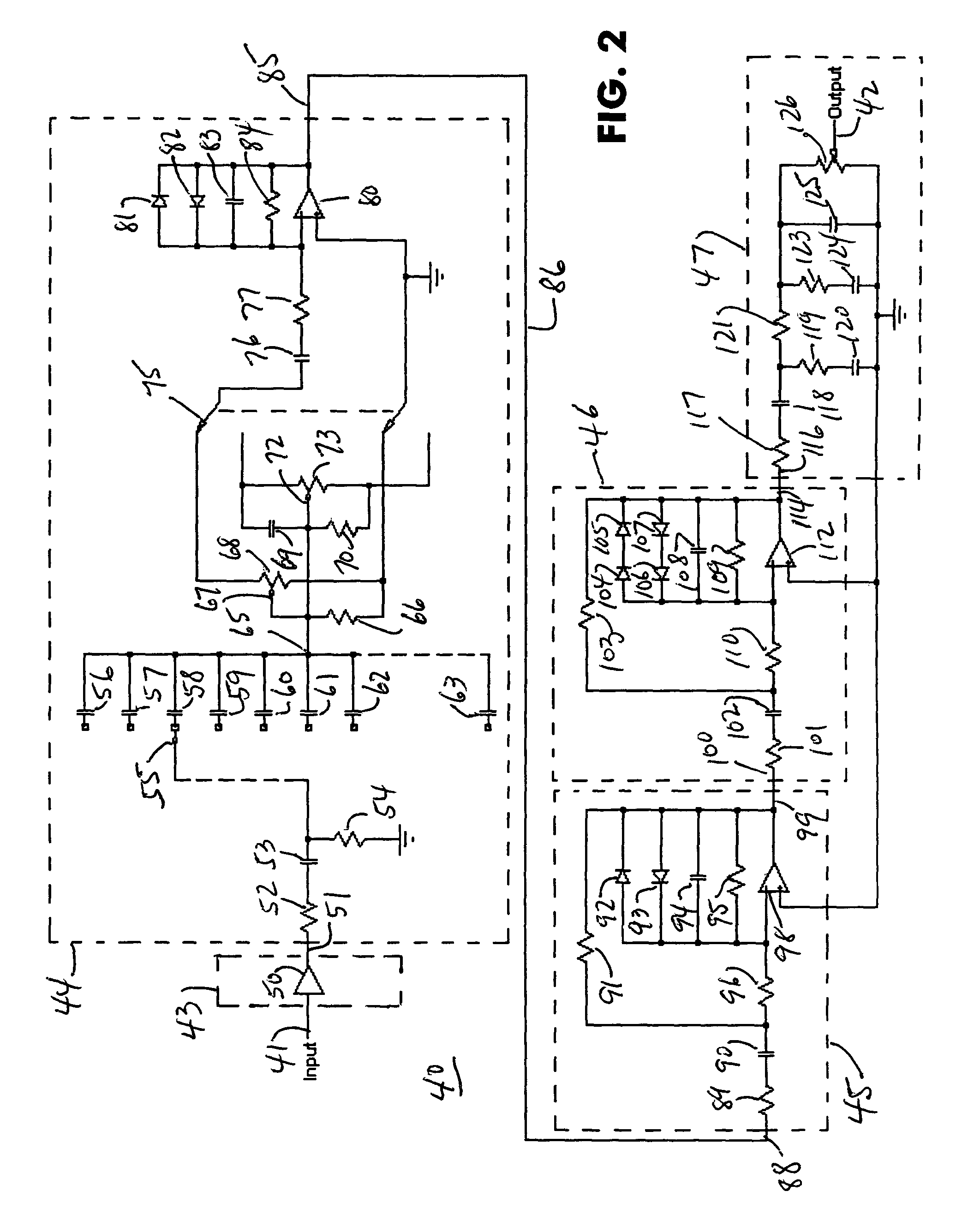
[0039]A preferred schematic for the signal processor circuit 40 is shown in FIG. 2 with the blocks identified in FIG. 1 shown in dashed lines about certain component...


PUM


Abstract

An electronic signal processor for processing signals includes a complex first filter, one or more gain stages and a second filter. The first filter is characterized by a frequency response curve that includes multiple corner frequencies, with some corner frequencies being user selectable. The first filter also has at least two user-preset gain levels which may be alternately selected by a switch. Lower frequency signals are processed by the first filter with at least 12 db / octave slope, and preferably with 18 db / octave slope to minimize intermodulation distortion products by subsequent amplification in the gain stages. A second filter provides further filtering and amplitude control. The signal processor is particularly suited for processing audio frequency signals. Related methods include filtering the input signal with an input filter of the second or third order high pass type, amplifying the filtered signal and further filtering the amplified signal with a low pass filter, which may be of the second order type.

Description

FIELD OF THE INVENTION[0001]The present invention relates generally to electronic signal processors. More particularly, a preferred embodiment of the invention relates to altering or controlling the tonal qualities of electronic signals, such as audio signals, and related methods.BACKGROUND OF THE INVENTION[0002]Various prior art devices exist for modifying the tonal qualities of electronic signals. In audio frequency applications, the types of signals processed can be speech, musical instruments, synthesized waveforms, and the like. Prior art devices for processing musical instrument signals generally have a very limited ability to provide the musician with a variety of tonal qualities in the resulting sound. For example, prior art circuits exist for processing electric guitar signals that have a singular tonal quality, or “sound”. This is a serious limitation, since the guitarist must frequently employ a plurality of different circuits if different “sounds” are desired.[0003]Some ...

Claims


Application Information

Patent Timeline
Patent Type & Authority Patents(United States)
IPC IPC(8): G10H1/18G10D1/08H02B1/00H03G3/00H03G5/00H03F3/04G10H1/46G10H1/00G10H1/06G10H1/12
CPCG10H3/187H03F3/68G10H1/12H03G7/001H03G5/025G10H2210/311G10H2220/265H03F3/181H03F2200/03H03G3/10
Inventor ARNOLD, JEFFREY
Owner ARNOLD JEFFREY
Why Eureka
Try Eureka