Data retention cell and data retention method based on clock-gating and feedback mechanism

a data retention and clock-gating technology, applied in the field of data retention cells and data retention methods based on clock-gating and feedback mechanisms, can solve the problems of power consumption of handheld devices significantly affecting battery life, and data signals of circuits being stored in flip-flops may be lost in power-saving mod

Active Publication Date: 2008-06-24
MARLIN SEMICON LTD
View PDF9 Cites 70 Cited by
  • Summary
  • Abstract
  • Description
  • Claims
  • Application Information

AI Technical Summary

Benefits of technology

[0008]In accordance with an embodiment of the present invention, a data retention cell is provided for preserving an output data signal in a power-saving mode. The data retention cell comprises an input control circuit and a master-slave flip-flop. The input control circuit has a first input port for receiving an input data signal, a second input port for receiving a retention signal, a third input port for receiving a clock, a fourth input port for receiving a feedback signal, a first output port for outputting an internal input data signal, and a second output port for outputting an internal clock. The input control circuit comprises a delay unit having an input port coupled to the second input port of the input control circuit for receiving the retention signal and an output port. The master-slave flip-flop has a first input port coupled to the first output port of the input control circuit for receiving the internal input data signal, a second input port coupled to the second output port of the input control circuit for receiving the internal clock, a first output port for outputting the output data signal, and a second output port for outputting the feedback signal. The master-slave flip-flop comprises a master latch unit having an input port and an output port, and a slave latch unit having an input port and an output port. The slave latch unit is coupled to be powered between a real supply voltage and a real ground voltage, and the master latch unit is coupled to be powered by a virtual power.
[0009]The present invention further provides a data retention cell for preserving a complemented output data signal in a power-saving mode. The data retention cell comprises an input control circuit and a master-slave flip-flop. The input control circuit has a first input port for receiving an input data signal, a second input port for receiving a retention signal, a third input port for receiving a clock, a fourth input port for receiving a feedback signal, a first output port for outputting an internal input data signal, and a second output port for outputting a complemented internal clock. The input control circuit comprises a delay unit having an input port coupled to the second input port of the input control circuit for receiving the retention signal and an output port. The master-slave flip-flop has a first input port coupled to the first output port of the input control circuit for receiving the internal input data signal, a second input port coupled to the second output port of the input control circuit for receiving the complemented internal clock, a first output port for outputting the complemented output data signal, and a second output port for outputting the feedback signal. The master-slave flip-flop comprises a master latch unit having an input port and an output port, and a slave latch unit having an input port and an output port. The slave latch unit is coupled to be powered between a real supply voltage and a real ground voltage and the master latch unit is coupled to be powered by a virtual power.
[0010]Furthermore, the present invention provides a data retention method for preserving an output data signal of a data retention cell in a power-saving mode. The data retention cell includes an input control circuit and a master-slave flip-flop. The data retention method comprises powering a slave latch unit of the master-slave flip-flop with a real power, powering a mater latch unit of the mater-slave flip-flop with a virtual power, switching a retention signal furnished to the input control circuit from a disable state to an enable state when receiving a power-saving request, decoupling the virtual power from the real power, retaining the output data signal in the slave latch unit of the master-slave flip-flop, furnishing the output data signal backward to the input control circuit, coupling the virtual power to the real power when receiving a power-active request, forwarding the retained output data signal by the input control circuit to the master latch unit of the master-slave flip-flop, switching the retention signal from the enable state to the disable state, and delaying signal refreshing of the master latch unit by an input data signal through the input control circuit.

Problems solved by technology

For instance, battery life is a very important consideration for the performance of handheld devices, and power consumption of handheld devices significantly affects the battery life.
However, states or data signals of a circuit being stored in flip-flops may be lost in the power-saving mode.

Method used


Image

  • Data retention cell and data retention method based on clock-gating and feedback mechanism
  • Data retention cell and data retention method based on clock-gating and feedback mechanism
  • Data retention cell and data retention method based on clock-gating and feedback mechanism

Examples


Embodiment Construction

[0019]Hereinafter, preferred embodiments of the present invention will be described in detail with reference to the accompanying drawings. For signal explanation, a logic state 1 is used to describe one logic state that assumes a high logic level, and a logic state 0 is used to describe the other logic state that assumes a low logic level. Here, it is to be noted that the present invention is not limited thereto.

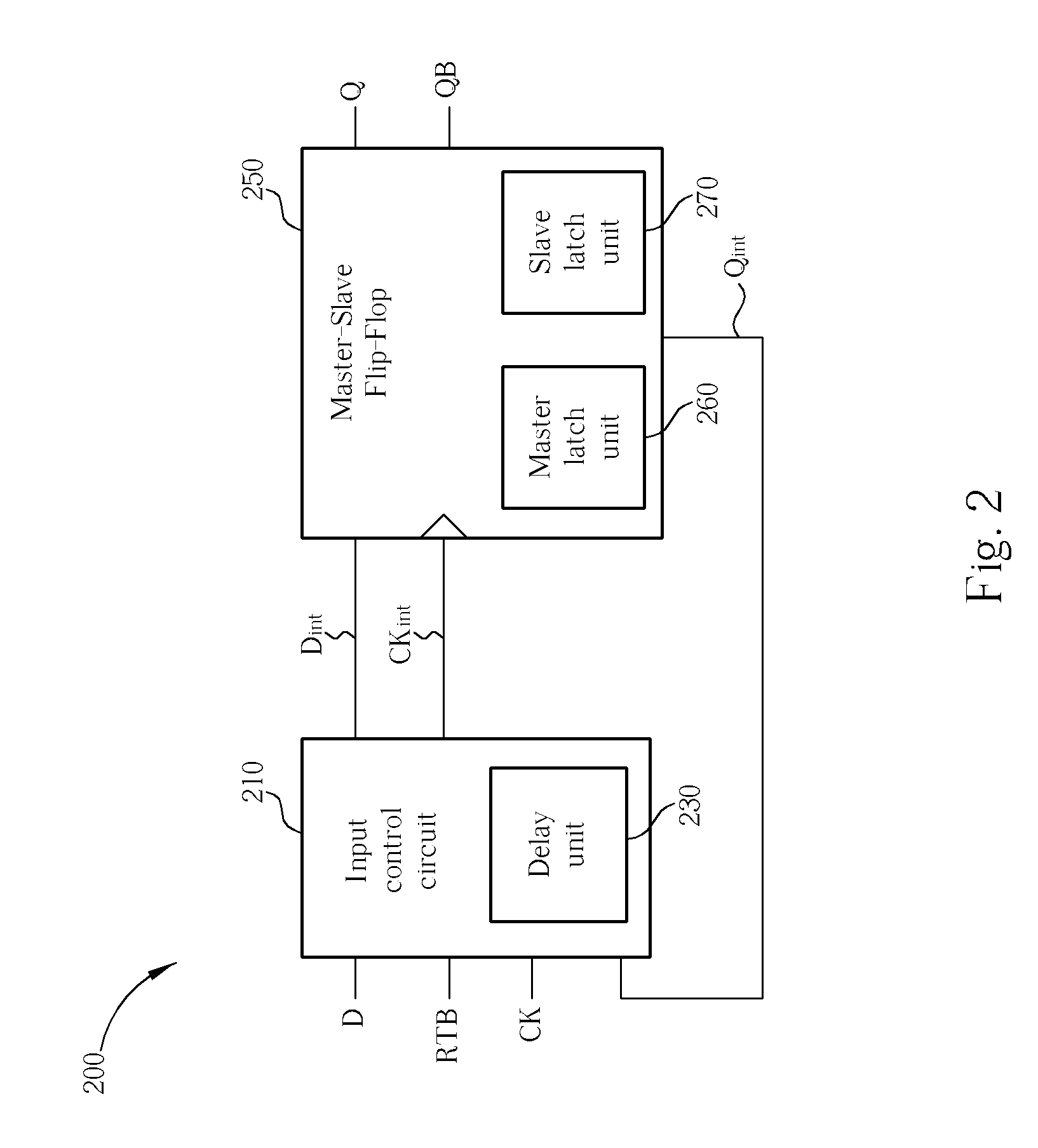
[0020]Please refer to FIG. 2, which is a block diagram schematically showing the structure of a data retention cell 200 according to the present invention. The data retention cell 200 comprises an input control circuit 210 and a master-slave flip-flop 250. The input control circuit 210 comprises a delay unit 210. The input control circuit 210 has a first input port for receiving an input data signal D, a second input port for receiving a retention signal RTB, a third input port for receiving a clock CK, a fourth input port for receiving a feedback signal Qint, a first output...


PUM


Abstract

For retaining an output data signal of a data retention cell in a power-saving mode, a slave latch unit of the data retention cell is powered with a real power for preserving the output data signal. The output data signal is furnished backward to an input control circuit of the data retention cell. The data signal furnished to a master latch unit of the data retention cell is controlled to switch between an input data signal and the output data signal by the input control circuit in response to a retention signal. The switching of the data signal for refreshing the master latch unit is delayed by a delay unit of the input control circuit, which functions to make sure that the data-preserving process is properly operated on any transition from the power-saving mode to a power-active mode.

Description

BACKGROUND OF THE INVENTION[0001]1. Field of the Invention[0002]The present invention relates to a data retention cell and a data retention method, and more particularly, to a data retention cell and a data retention method based on clock-gating and feedback mechanism.[0003]2. Description of the Prior Art[0004]Lower power consumption has become a big demand for devising integrated circuits mainly due to wide spread use of portable and handheld applications. For instance, battery life is a very important consideration for the performance of handheld devices, and power consumption of handheld devices significantly affects the battery life. In order to reduce power consumption, integrated circuits can be operated in a power-saving mode by switching-off the power during standby operating, which can be done by decoupling either the supply voltage or the ground voltage provided to the integrated circuits.[0005]The transistor used for controlling the coupling situation concerning the suppl...

Claims


Application Information

Patent Timeline
Patent Type & Authority Patents(United States)
IPC IPC(8): H03K3/356
CPCH03K3/0375H03K3/3562
Inventor CHUANG, FU-CHAI
Owner MARLIN SEMICON LTD
Why Eureka
Try Eureka