Method of using scan chains and boundary scan for power saving

a technology of scan chains and boundary scans, applied in the direction of liquid/fluent solid measurement, high-level techniques, instruments, etc., can solve the problems of consuming more dynamic power, affecting the efficiency of the process, so as to improve the process technology of methods 1 and 3 and achieve the effect of improving the process technology

Inactive Publication Date: 2008-06-24
PRINCETON TECH CORP
View PDF1 Cites 35 Cited by
  • Summary
  • Abstract
  • Description
  • Claims
  • Application Information

AI Technical Summary

Benefits of technology

[0015]It is therefore an object of the present invention to provide a method and circuitry by utilizing the existing Scan Chains / Boundary Scan (EE.1149.1) technologies for gated power to reduce the hardware overhead for power saving in synchronous logic ASIC. A controller is embedded in a synchronous logic ASIC, and let org_s_mode, org_s_enable, org_bs_mode, org_bs_enable, power_off, clock and reset signals of the scan chains and boundary scan circuits to be inputted into the controller and generate a new set of control signals of s_mode, s_enable, bs_mode, bs_enable, pw_switch, scan_clock, bs_clock, mem_if to control the scan chains and boundary scan circuits such that:

Problems solved by technology

In deep sub-micron and portable circuit design, the leakage current becomes a major factor in power consumption.
As to the method 3 stated above, a high VT might increase short circuit current, which may consume more dynamic power.
Moreover, methods 1 and 3 must improve the process technologies, are expensive and progress slowly.
For a portable device more than 95% of the mission time is in the standby mode, so leakage current is one of the dominant factors for the power consumption.
However, method 4 of gated power has not been widely used, because of the following two reasons:1. Gated power needs extra memories, control circuits, and routing wires to save the contents of a power-off block.
Too much hardware overheads are involved.2. The power-off / power-on sequences are very trivial.

Method used


Image

  • Method of using scan chains and boundary scan for power saving
  • Method of using scan chains and boundary scan for power saving
  • Method of using scan chains and boundary scan for power saving

Examples


Embodiment Construction

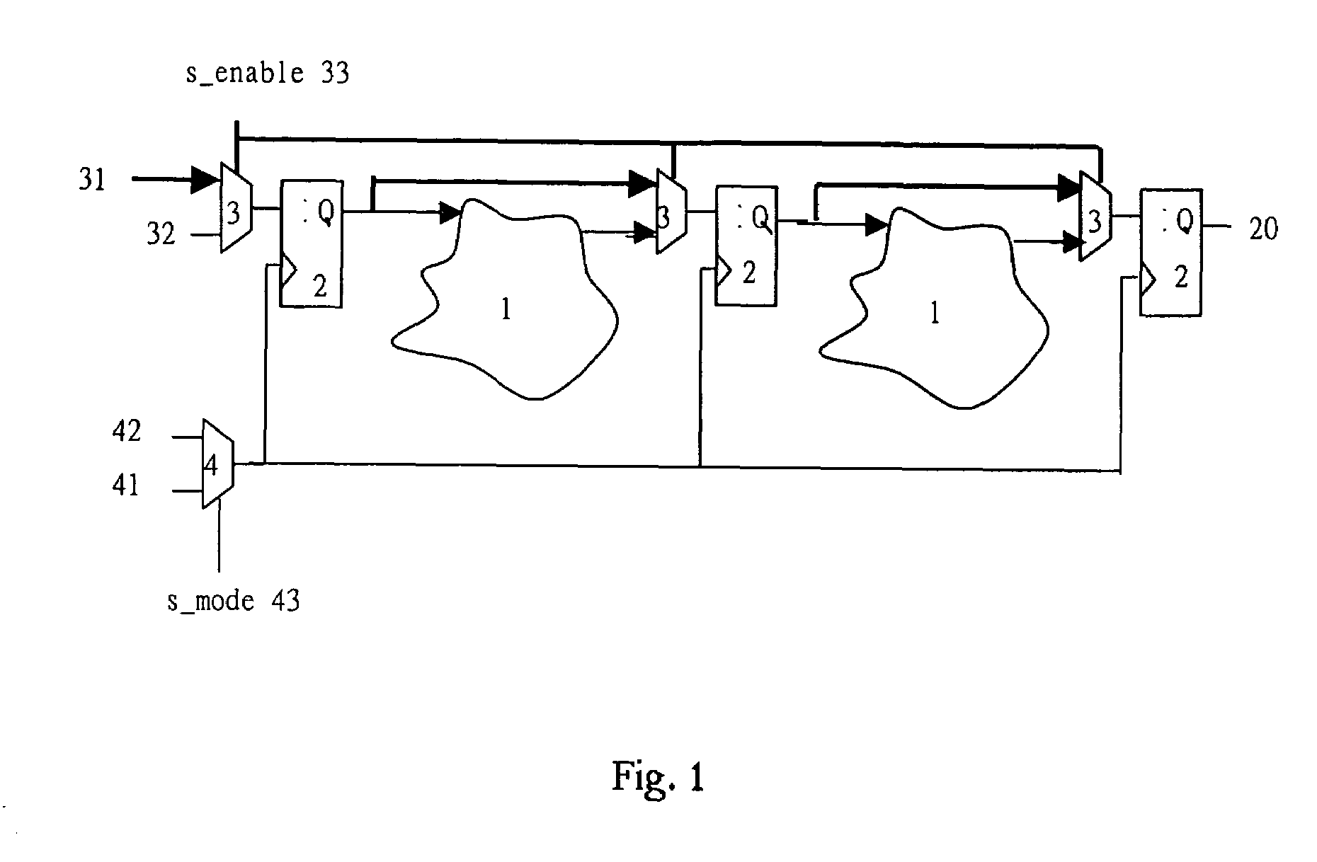
[0031]Referring to the FIG. 1, a typical section of a production test Scan Chains is shown. In a synchronous logic ASIC, Scan Chains circuit will be added along with the main circuit. The main circuit comprises many combinational logic circuits 1 and many memory-type devices 2 (such as flip-flops, shift-registers). Scan Chain circuit comprises mutiplexer 3 and 4. Multiplxer 3 has two inputs “test 31” and “operation 32”, while multiplexer 4 has two inputs “scan clock 41” and “main clock 42”. When the control signals of s_enable 33 and s_mode 43 of the multiplexer 3 and 4 are pulled low, the “operation 32” and “main clock 42” will be inputted to the synchronous logic ASIC for normal operation. When the control signals of s_enable 33 and s_mode 43 of the multiplexer 3 and 4 are pulled high, the circuit goes into the scan mode for production test. The scan clock 41 will replace the main clock 42 to be inputted into the synchronous logic ASIC. The data of “test 31” will be shifted into t...


PUM


Abstract

The invention provides a method and circuitry to save power in a synchronous logic ASIC with low overhead. The scan chain(s) and boundary scan mechanism of the synchronous logic ASIC are used and modified for shifting out current states of internal memory devices of the synchronous logic ASIC to an external memory and for retaining the power-off blocks' primary output values to the memory devices of the boundary scan circuit, so the proposed gated power method is efficient and low overhead in the synchronous, flop-based, logic circuit design.

Description

FIELD OF THE INVENTION[0001]The present invention relates to a method for reducing the leakage current in synchronous logic ASIC, and more particularly to a method by using technologies of Scan Chains and Boundary Scan (IEEE 1149.1) for power saving.BACKGROUND OF THE INVENTION[0002]Power saving is getting more and more important in recent integrated circuit design for all portable applications (for example, PDA, laptop computer, cellular phone . . . etc.). The power consumption can be categorized into two main categories: dynamic power consumption (switching power, P=CV2f), and static (leakage) power consumption.[0003]For the dynamic power consumption, two techniques have been applied to reduce the power consumption by reducing C, V, and / or f (total capacitance, supplied voltage and / or operation frequency):[0004]1. Improve processing technology, so both the supplied voltage and the circuit area / capacitance are reduced (reducing C and V).[0005]2. Gated clock. Turn off the clock to re...

Claims


Application Information

Patent Timeline
Patent Type & Authority Patents(United States)
IPC IPC(8): G01R31/28
CPCG01R31/318575G06F1/32G06F1/3203G06F1/3237Y02B60/1221Y02B60/32Y02D10/00Y02D30/50
Inventor TANG, YING YUANCHEN, YUNG SENKAO, DE YU
Owner PRINCETON TECH CORP
Why Eureka
Try Eureka