Method for automatically mapping of geometric objects in digital medical images

a technology of digital medical images and geometric objects, applied in image enhancement, color signal processing circuits, instruments, etc., can solve the problems of large number of mouse manipulations, slow method, fatiguing and error-prone, etc., and achieve the effect of constant radiographic finding

Active Publication Date: 2008-07-01
AGFA NV
View PDF8 Cites 93 Cited by
  • Summary
  • Abstract
  • Description
  • Claims
  • Application Information

AI Technical Summary

Benefits of technology

[0016]A further characteristic of the model anchor objects is that their number will typically be small, but sufficient to enable accurate positioning of the geometrical objects. More anchor objects than needed to derive the geometric transform may be selected when they are considered topologically relevant. In that case, an over-determined solution is derived that fits a geometric transformation by minimizing e.g. a least-squares criterion.

Problems solved by technology

A typical exposure error introducing positional variation is that the hand axis is placed in a rotated fashion with respect to the cassette borders of a cassette conveying a radiation detector such as a photo-stimulable phosphor screen on which the radiation image is recorded.
Obviously, in the film-based measurements, no assistance is offered in drawing the geometric objects or entities in the image.
However, the drawback of this manner of operation is that when the number of key user points is large, which is typically the case for complex measurement schemes, a large number of mouse manipulations is needed, hence this method is slow, fatiguing and error prone.

Method used


Image

  • Method for automatically mapping of geometric objects in digital medical images
  • Method for automatically mapping of geometric objects in digital medical images
  • Method for automatically mapping of geometric objects in digital medical images

Examples


second embodiment

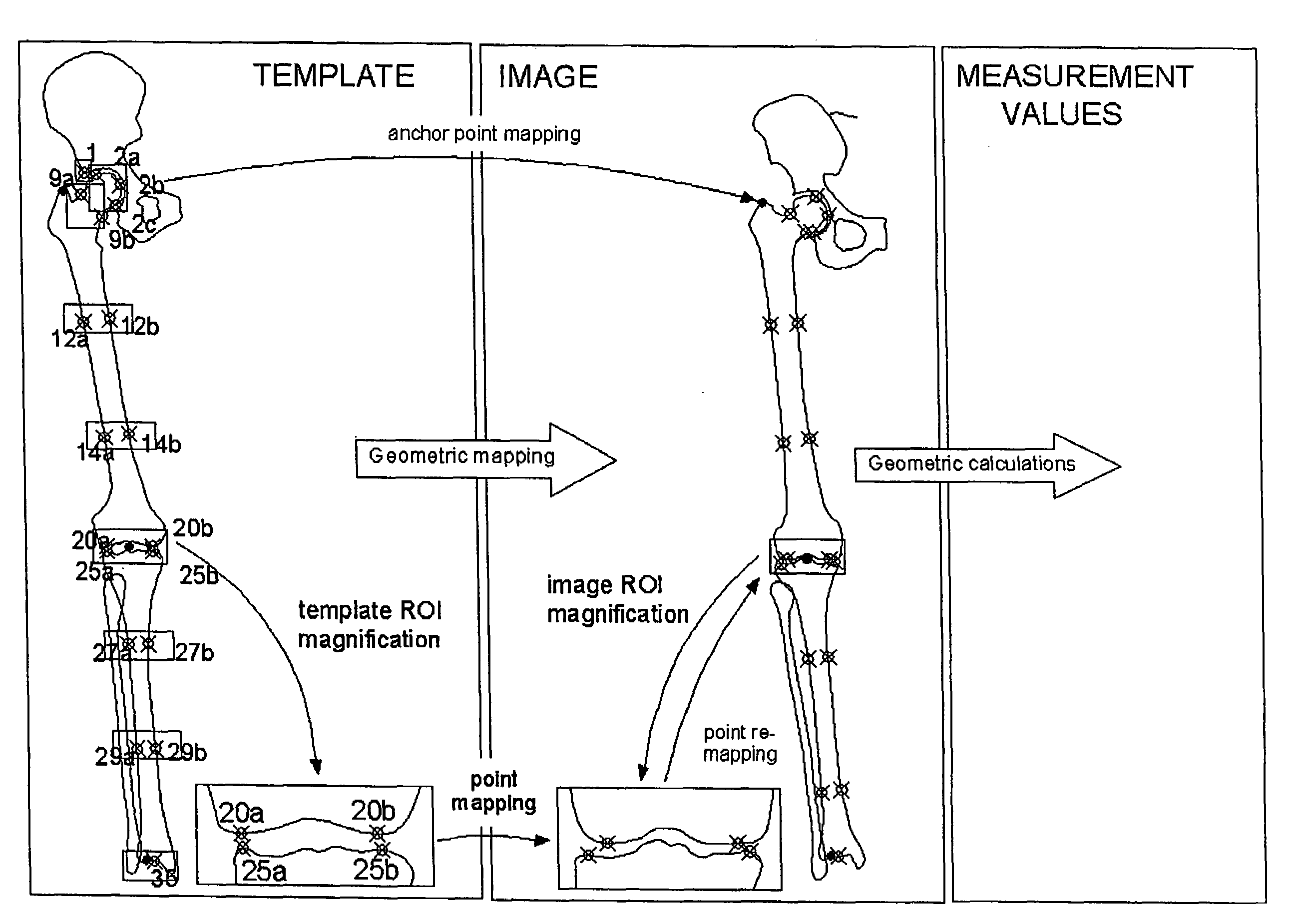
[0254]Instead of extracting ROIs from the image to be scored and presenting them in juxtaposed to the reference pictures, an second embodiment, that uses the spatial mapping operation based on anchor points, consists in mapping the reference pictures into the image, in close vicinity to the skeletal region (e.g. in a touching manner to the ROI of a particular region). Using the scroll wheel of the mouse, or the up and down keys of the keypad, the reference pictures are scrolled through, and the user selects that reference stage corresponding to the largest similarity between reference picture and skeletal region. This manner of operation has the advantage that the full input image remains visible to the user.

third embodiment

[0255]The ROI and reference picture mapping is further advantageous in a third embodiment based on registration where similarity is measured by pixel-wise comparison based on correlation. In this embodiment the reference picture is mapped into the image in a spatially coinciding manner so as to overlay on the corresponding skeletal site. The anchor points with respect to which the skeletal regions are referenced are used to superimpose the reference picture onto the skeletal region to be scored. A linear or non-linear image registration operation is applied to the ROI to find its most corresponding position with respect to the skeletal site and the degree of similarity of the registration is recorded. This registration operation is repeated for each of the reference pictures, and that stage is selected for which the degree of similarity is the highest.

Radiological Image Quality Control

[0256]The current invention is further particular useful in the context of quality control and qual...


PUM


Abstract

A method of mapping geometrical objects to a digital image. At least one anchor point in a model is selected and mapped to the digital image. A geometric transformation is computed on the basis of at least one correspondence between an anchor object and a corresponding mapped object, and the calculated geometric transformation is applied to at least one geometric object thereby mapping it from the model image to a corresponding mapped position in the digital image.

Description

[0001]This application claims the benefit of U.S. provisional application No. 60 / 582,335, filed Jun. 22, 2004, which is incorporated by reference.FIELD OF THE INVENTION[0002]The present invention relates to computer-assisted method to map geometric objects in a digital medical image.BACKGROUND OF THE INVENTION[0003]In radiological practice, the radiographer frequently needs to locate specific anatomic structures on the radiograph in order to focus his attention on these specific image areas. The position of the image areas will typically depend on the examination type of the radiograph and the suspected disease; hence these locations are examination and diagnosis-specific.[0004]For example, in bone age assessment according to the Tanner-Whitehouse method, 20 bony regions of interest (ROI) need be located on a hand radiograph, and staged against a set of reference stages depicted in an atlas. In European patent application EP A 1 293 925, a method is disclosed to automate the staging...

Claims


Application Information

Patent Timeline
Patent Type & Authority Patents(United States)
IPC IPC(8): G06K9/36G09G5/00H04N9/74G06K9/00G06T7/00G06T7/60G06T15/00
CPCG06T7/606G06T7/0046A61F2002/4633G06T2207/30008G06T7/66G06T7/75
Inventor DEWAELE, PIET
Owner AGFA NV
Why Eureka
Try Eureka