
Renewable energy electric power generating system

a technology of electric power generation system and renewable energy, which is applied in the direction of electric generator control, machine/engine, greenhouse gas reduction, etc., can solve the problems that the economic potential of high temperature superconducting wind turbine technology has not been fully exploited, and achieve the effect of increasing off-peak use and capacity

Inactive Publication Date: 2008-07-08
COOPER WILLARD
View PDF100 Cites 38 Cited by
  • Summary
  • Abstract
  • Description
  • Claims
  • Application Information

AI Technical Summary

Benefits of technology

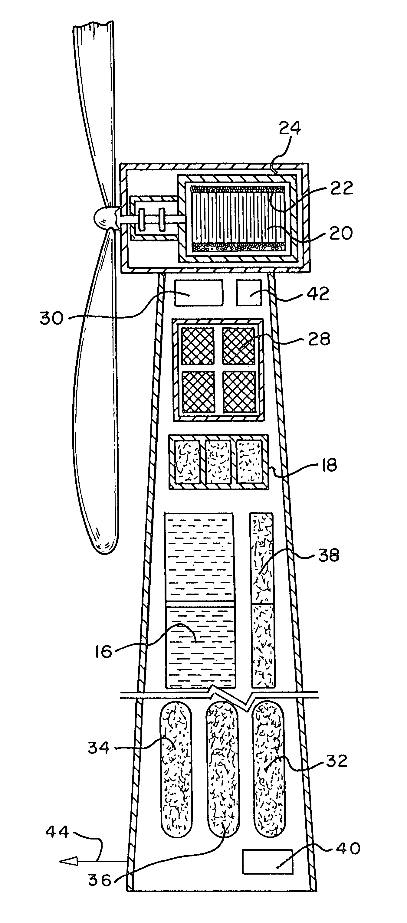
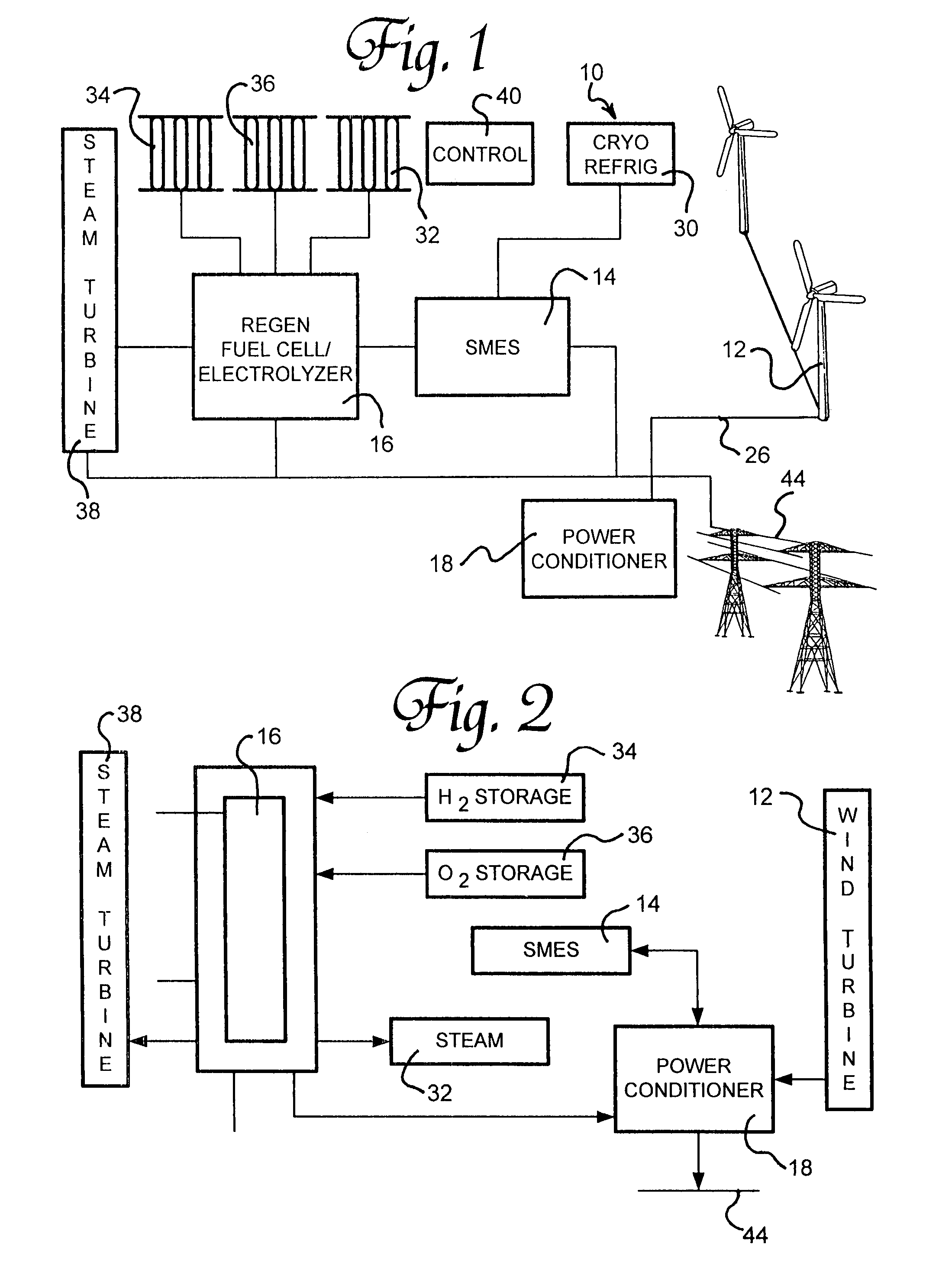
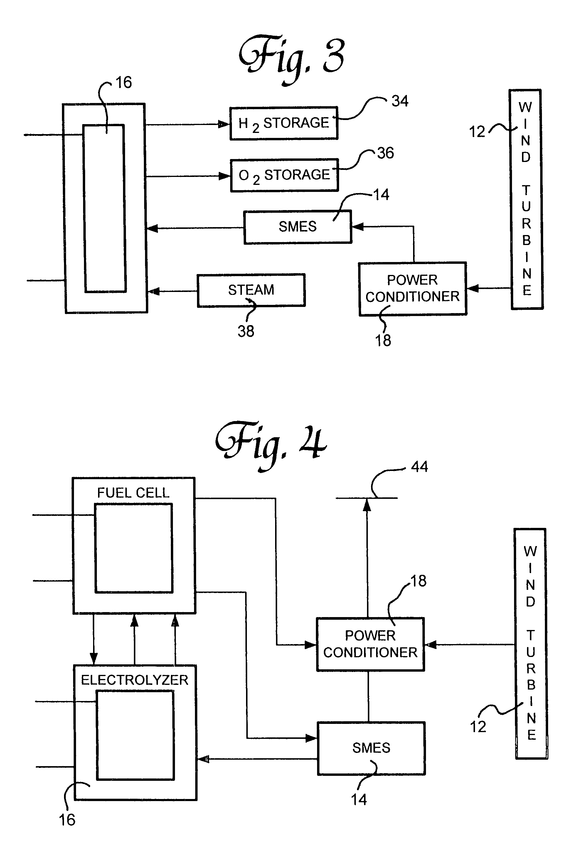
"The present invention is a concept for meeting America's growing energy demand through the use of non-polluting electric generating technology utilizing renewable energy. The invention integrates three major advanced energy technologies to significantly enhance their overall efficiency for the production of electric power. These technologies include a high temperature superconducting wind turbine generator, a high temperature superconducting magnetic energy storage system, and either a regenerative or a modified interactive solid oxide fuel cell / electrolyzer. The integrated system is designed to operate on a managed day / night or 24-hour cycle, and can generate electricity and hydrogen and oxygen at different times of the day or night, depending on demand. The system employs a multi-use cryorefrigeration system to cool the current carrying high temperature superconducting cables and the wind turbine generator coils and bearings, as well as the magnetic energy storage units. The modified solid oxide interactive system does not require hydrogen, oxygen, or high temperature steam storage systems but would require larger capacity superconducting energy storage units for increased off-peak use."

Problems solved by technology

However, the economic potential of high temperature superconducting wind turbine technology has not been fully exploited particularly when operationally integrated with a regenerative solid oxide fuel cell / electrolyzer system to operate on a day / night cycle.

Method used


Image

  • Renewable energy electric power generating system
  • Renewable energy electric power generating system
  • Renewable energy electric power generating system

Examples


Embodiment Construction

[0018]Referring now to the drawings in detail wherein like reference numerals have been used throughout the various figures to designate like elements, there is shown in the FIGS. 1, 2 and 5 a renewable energy electric power generating system constructed in accordance with the principles of the present invention and designated generally as 10. The general arrangement of the various components of an integrated large-scale renewable energy power generating system 10 is illustrated in FIG. 1. However, the specific details of the high temperature superconducting wind turbine generator are illustrated in FIG. 5, which is a schematic view of a vertically integrated renewable energy power generating system housed within a stand-alone wind turbine structure.

[0019]The renewable energy electric power generating system 10 is comprised of three major components incorporating advanced energy technologies that are uniquely integrated so as to significantly enhance their overall efficiency for the...


PUM


Abstract

A renewable electric power system includes a high temperature superconducting wind turbine using high temperature superconducting yttrium-barium-copper oxide for the rotor and stator windings as well as a superconducting bearing. Power from the turbine is stored in a high temperature superconducting magnetic storage system that also uses HTS YBCO. Also included is a regenerative solid oxide fuel cell / electrolyzer with steam turbine cogeneration. The system operates on a managed day / night cycle. During daytime, the energy produced by the wind turbines and fuel cells is transmitted to the grid. During nocturnal hours, the wind turbine is used to provide low cost electricity to the reversible fuel cells operating in the electrolysis mode producing hydrogen and oxygen that is stored for later use. Alternatively, the fuel cells can remain in electrolysis mode producing hydrogen and oxygen for the market. A modified interactive system generates power on a continuous twenty-four hour cycle.

Description

CROSS-REFERENCE TO RELATED APPLICATION[0001]This application is a division of U.S. patent application Ser. No. 11 / 253,106, filed Oct. 18, 2005, now U.S. Pat. No. 7,233,079.BACKGROUND OF THE INVENTION[0002]The present invention is directed toward a renewable energy electric power generating system and, more particularly, toward an integrated renewable energy system comprised of high temperature superconducting wind turbines and regenerative or interactive solid oxide fuel cells / electrolyzers with superconducting magnetic energy storage based on a managed demand cycle.[0003]The world is facing a major energy and clean air challenge. Renewable energy systems using wind, sun, and water and utilizing advanced energy generating technology offer some potential solutions. Unfortunately, the current state of the art of conventional wind turbine generators, energy storage systems, as well as fuel cell / electrolyzer technologies have individually not been fully developed from a standpoint of ef...

Claims


Application Information

Patent Timeline
Patent Type & Authority Patents(United States)
IPC IPC(8): F03D9/00H02P9/04
CPCF03D9/021H02J3/28H01M8/186Y02E10/763Y02E10/72Y02E10/766Y02E20/16Y02E40/67Y02E70/10Y02E70/20Y02E70/30H01M2250/10H01M2250/405H01M2250/407Y02E60/528Y02B90/14Y02E60/563Y02B90/16H02J3/383H02J3/386Y02E10/563Y02E10/566F05B2220/61F03D9/11F03D9/257H02J2300/28H02J2300/24H02J3/381Y02B90/10Y02E10/56Y02E10/76Y02E40/60Y02E60/50Y02E60/36H02J2300/30
Inventor COOPER, WILLARD
Owner COOPER WILLARD
Learn More