Dynamically-adjustable differential output drivers

a differential output and driver technology, applied in the field of inputoutput (i/o) circuitry, can solve the problems of communication path subject to undesirable effects, undesirable noise, undesirable effects, etc., and achieve the effect of reducing dc current flow and enhancing the compatibility of output drivers with receivers in the system

Inactive Publication Date: 2008-07-08
TAHOE RES LTD
View PDF20 Cites 22 Cited by
  • Summary
  • Abstract
  • Description
  • Claims
  • Application Information

AI Technical Summary

Benefits of technology

[0024]With the dynamically adjustable differential output driver, output driver compatibility with receivers in the system can be enhanced. A programmable logic device or other integrated circuit may have multiple different data channels, each with a different system environment and different optimum VCM and VOD settings (even if some of these channels are operated using the same nominal differential signaling standard). Potential mismatches between the common-mode voltage of each output driver and each corresponding input driver on another circuit can be minimized by adjusting the VCM on each channel separately, which helps to reduce DC current flow along signal paths in DC-coupled arrangements.
[0025]Optimizing the common-mode voltages and differential output voltages also helps to ensure that the output drivers and input drivers can communicate properly. It is not necessary to reconfigure a programmable logic device that contains dynamically-adjustable output drivers to make the desired signal level changes, because driver adjustments can be made dynamically based on real-time control signals. The dynamically-adjustable differential output driver arrangement provides system designers with the flexibility to adjust output driver parameters based on diverse system requirements.

Problems solved by technology

However, in some situations such as when communications paths are packed densely or when the signals are large, a communications path may be subject to the undesirable effects of crosstalk.
In other situations, such as when the I / O signals are weak or when the length of the communications path is large, there may be undesirable noise present.
These undesirable effects may arise even at values of VCM and VOD that fall within a prescribed signaling standard range.

Method used


Image

  • Dynamically-adjustable differential output drivers
  • Dynamically-adjustable differential output drivers
  • Dynamically-adjustable differential output drivers

Examples


Embodiment Construction

[0037]The present invention relates to adjustable differential output drivers. The invention also relates to the integrated circuits and systems with which such differential output drivers are used and methods for controlling and using these components.

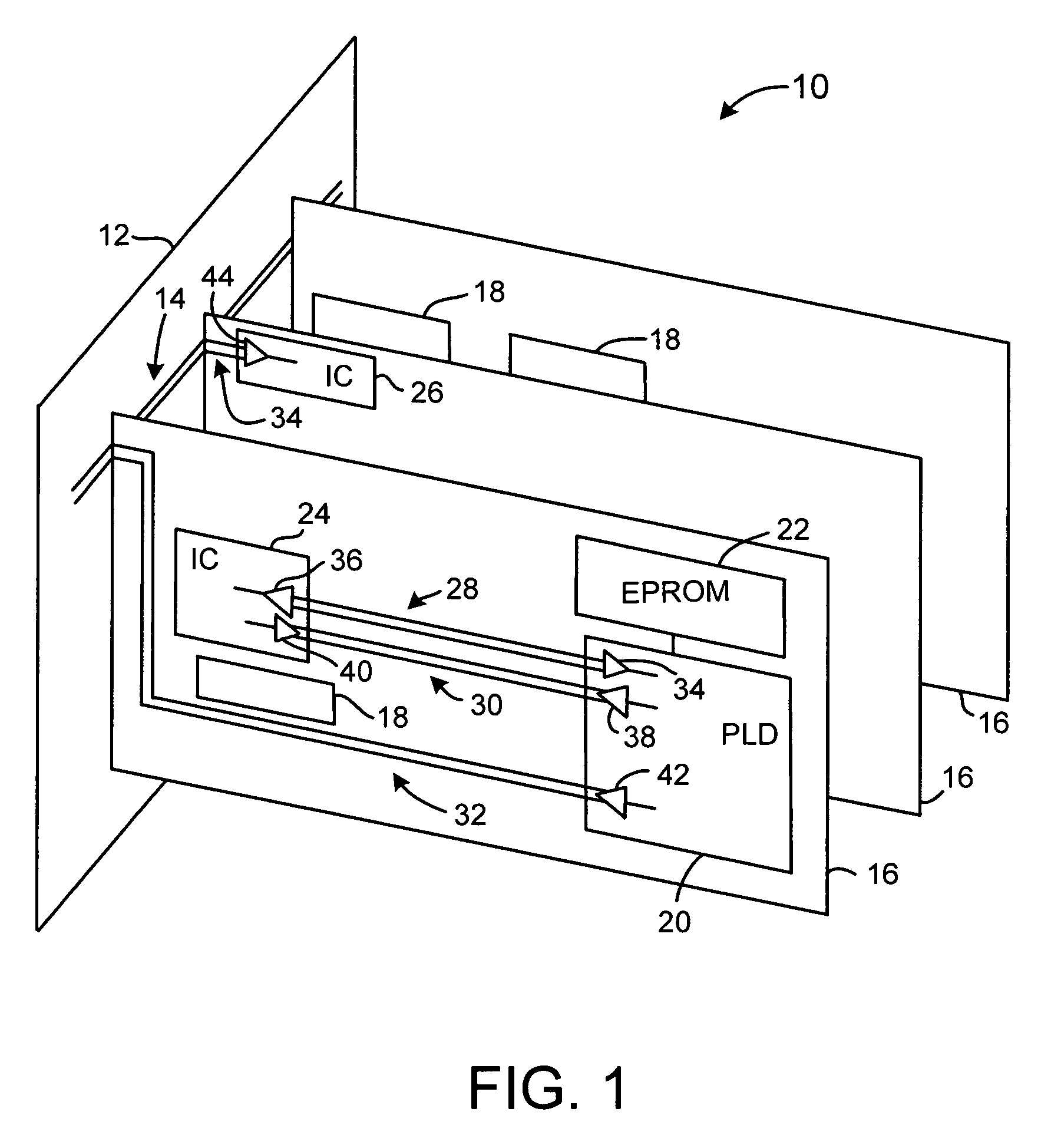
[0038]An illustrative system 10 in accordance with the present invention is shown in FIG. 1. In the illustrative system of FIG. 1, a backplane 12 having a bus 14 is used to interconnect a number of circuit boards 16. The bus 14 of FIG. 1 is shown as having only two conductive lines, but busses such as bus 14 typically have many more such lines. These additional lines are not shown in FIG. 1 to avoid over-complicating the drawing.

[0039]One or more backplanes such as backplane 12 and circuit boards 16 may be mounted in a system rack or installed in another suitable housing. Circuit boards 16 may be line cards in a telecommunications system, may be circuit boards in a computer, or may be any other module or submodule in a larger system. ...


PUM


Abstract

Systems and methods are provided using dynamically adjustable differential output drivers. Integrated circuits such as programmable logic devices may be provided with adjustable differential output drivers for transmitting high-speed data to other integrated circuits. The peak-to-peak output voltage and common-mode voltage of the output drivers may be adjusted. Dynamic control circuitry may be used to control the settings of current sources, programmable resistors, and voltage source circuitry in the adjustable differential output driver automatically in real time. The adjustable components in the differential output driver may be adjusted by the dynamic control circuitry based on feedback information received from the integrated circuit to which the data is transmitted.

Description

[0001]This application is a continuation of patent application Ser. No. 10 / 670,146, filed Sep. 24, 2003, now U.S. Pat. No. 6,943,588 which is hereby incorporated by reference herein in its entirety.BACKGROUND OF THE INVENTION[0002]This invention relates to input-output (I / O) circuitry for integrated circuits, and more particularly, to differential output drivers that may be adjusted dynamically during circuit operation.[0003]Input-output (I / O) circuitry is used on integrated circuits as an interface between the circuitry on the integrated circuit and external components. Input-output circuitry typically includes either single-ended or differential input drivers and single-ended or differential output drivers.[0004]Single-ended drivers are used to handle single-ended signals—i.e., signals that are referenced to ground.[0005]Differential drivers are used to handle differential signals, which are carried on pairs of conductors. Differential signals are referenced to each other, rather ...

Claims


Application Information

Patent Timeline
Patent Type & Authority Patents(United States)
IPC IPC(8): H03K19/094
CPCH03K19/00369H03K19/01812H03K19/018585H03K19/018514H03K19/01837
Inventor LUO, MEISHUMARAYEV, SERGEYWONG, WILSONLEE, CHONG H.
Owner TAHOE RES LTD
Why Eureka
Try Eureka