
Optical disk device capable of preventing collision between disk and objective lens, and control method thereof

a technology of optical disk and objective lens, which is applied in the direction of digital signal error detection/correction, instruments, recording signal processing, etc., can solve the problems of difficult position control of the objective lens through the use of actuators, the member itself may oscillate, etc., and achieve the effect of preventing collision

Inactive Publication Date: 2008-07-08
FUNAI ELECTRIC CO LTD
View PDF18 Cites 1 Cited by
  • Summary
  • Abstract
  • Description
  • Claims
  • Application Information

AI Technical Summary

Benefits of technology

[0007]The present invention has been made in light of the foregoing situations, and an object of the present invention is to prevent collision between an objective lens and a disk reliably in an optical disk device.
[0015]According to the present invention, the position control of the holder by means of the actuator is stopped when the impact applied to the holder exceeds a prescribed value. Oscillation of the holder is prevented even when the holder receives an impact exceeding the range of normal displacement by the actuator, and thus, it is possible to avoid the situation where the subsequent position control by the actuator becomes difficult. Accordingly, the collision between the objective lens and the disk is prevented reliably.
[0016]Further, according to the present invention, when the impact applied to the holder exceeds a prescribed value, the position of the holder is controlled to make the objective lens move away from the disk, only after vibration of the holder abates. This further ensures prevention of the collision between the objective lens and the disk.
[0017]Still further, according to the present invention, the prescribed value used as the reference of the impact applied to the holder is set appropriately. As such, the collision between the objective lens and the disk can be prevented still more reliably.

Problems solved by technology

Conventionally, in the case where the position of the objective lens is controlled by a signal applied to an actuator, when a member holding the objective lens suffers an impact exceeding the range of normal displacement by the actuator, the member itself may oscillate, in which case subsequent position control of the objective lens by means of the actuator may be difficult.

Method used


Image

  • Optical disk device capable of preventing collision between disk and objective lens, and control method thereof
  • Optical disk device capable of preventing collision between disk and objective lens, and control method thereof
  • Optical disk device capable of preventing collision between disk and objective lens, and control method thereof

Examples


Embodiment Construction

[0024]Hereinafter, an information recording and reproduction apparatus as an embodiment of the present invention will be described in detail with reference to the drawings.

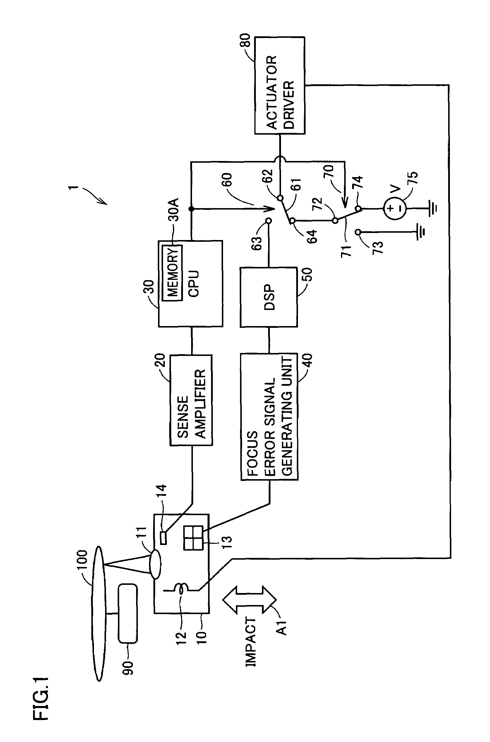
[0025]Referring to FIG. 1, the information recording and reproduction apparatus 1 is capable of writing and reading information to and from a disk 100. Information recording and reproduction apparatus 1 includes, among others, a pickup 10, a sense amplifier 20, a central processing unit (CPU) 30, a focus error signal generating unit 40, a digital signal processor (DSP) 50, switches 60, 70, an actuator driver 80, and a disk motor 90. CPU 30 has a memory 30A for storing various data. Disk motor 90 is provided to rotate disk 100 as appropriate.

[0026]Pickup 10 irradiates disk 100 with light by means of a mechanism (not shown), and receives reflected light from disk 100 via an objective lens 11. Pickup 10 can record information on disk 100 by means of a mechanism (not shown) as well. In pickup 10, the reflected light o...


PUM


Abstract

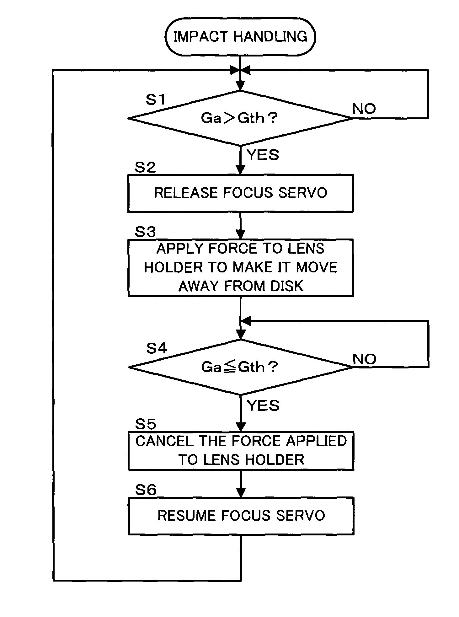
The magnitude (Ga) of an impact applied to a lens holder is constantly monitored based on an output of an impact sensor. When it is determined that Ga exceeds Gth, focus servo is released, and the lens holder is provided with a force to make it move away from a disk. Upon recheck of Ga, when it is determined that Ga is now equal to or less than Gth, the force having been provided to the lens holder is cancelled, and the focus servo is resumed.

Description

BACKGROUND OF THE INVENTION[0001]1. Field of the Invention[0002]The present invention relates to an optical disk device and a control method thereof, and more particularly to an optical disk device permitting control for preventing collision between a disk and an objective lens and a control method thereof.[0003]2. Description of the Background Art[0004]Conventionally, in an optical disk device, reading of information recorded on a disk from light reflected from the disk via an objective lens has been performed. Some of such optical disk devices are provided with an actuator for displacement of the objective lens, where a signal to be applied to the actuator is controlled so as to control the position of the objective lens in the focus direction.[0005]For position control of an objective lens in a focus direction for an optical pickup in an optical disk device, various techniques have conventionally been disclosed for preventing collision between the disk and the objective lens. For...

Claims


Application Information

Patent Timeline
IPC IPC(8): G11B7/09G11B21/12G11B7/085
CPCG11B7/0946G11B7/1201G11B11/1055G11B7/121
Inventor TACHIBANA, TADASHI
Owner FUNAI ELECTRIC CO LTD
Learn More