Miter saw having a light beam alignment system

a technology of light beam and alignment system, which is applied in the field of miter saws, can solve the problems of ruined workpieces, inability to know if the alignment of saws is correct, and a great deal of skill, and achieve the effect of facilitating alignmen

Inactive Publication Date: 2008-07-15
EASTWAY FAIR
View PDF132 Cites 12 Cited by
  • Summary
  • Abstract
  • Description
  • Claims
  • Application Information

AI Technical Summary

Benefits of technology

[0015]According to yet another aspect of the invention, the miter saw includes an arbor having an arbor base with a first mounting surface. A light source has a housing including a second mounting surface. The first and second mounting surfaces are secured together in a range of angular orientations for precisely aligning the light source. The mounting surfaces may be arcuate surfaces to facilitate alignment. The first and second surfaces may be secured together by a set screw or by a bonding agent. When the light source is rotated by the motor in conjunction with the blade, it emits a narrow beam of light adjacent the blade for providing a visual indication of the alignment of the blade with the workpiece.

Problems solved by technology

A common problem with miter saws is that it takes a great deal of skill to consistently align the workpiece with the saw blade so that the saw blade cuts at the desired location and at the desired angle.
With prior miter saws, it has not been possible to know if the saw alignment is proper until the saw begins to cut the material.
If the workpiece is not set up at the correct location with the correct angular orientation, the workpiece may be ruined if it is not properly aligned when the saw blade contacts the workpiece.
The Kelly patent does not disclose any shielding to prevent the laser from being directed into an operators eyes.
The Caluori patent likewise fails to disclose any shielding that prevents the laser from shining into an operator's eyes.
Both patents also fail to disclose an effective approach to preclude inadvertent operation of the laser when the arbor is disassembled.
Furthermore, both patents fail to disclose a system for precisely aligning the laser with the point at which the blade cuts into the workpiece.
The O'Banion patent does not disclose or suggest a laser arbor for a rotary saw or any reason to combine the louvered blade guard disclosed with a laser alignment device.

Method used


Image

  • Miter saw having a light beam alignment system
  • Miter saw having a light beam alignment system
  • Miter saw having a light beam alignment system

Examples


Embodiment Construction

)

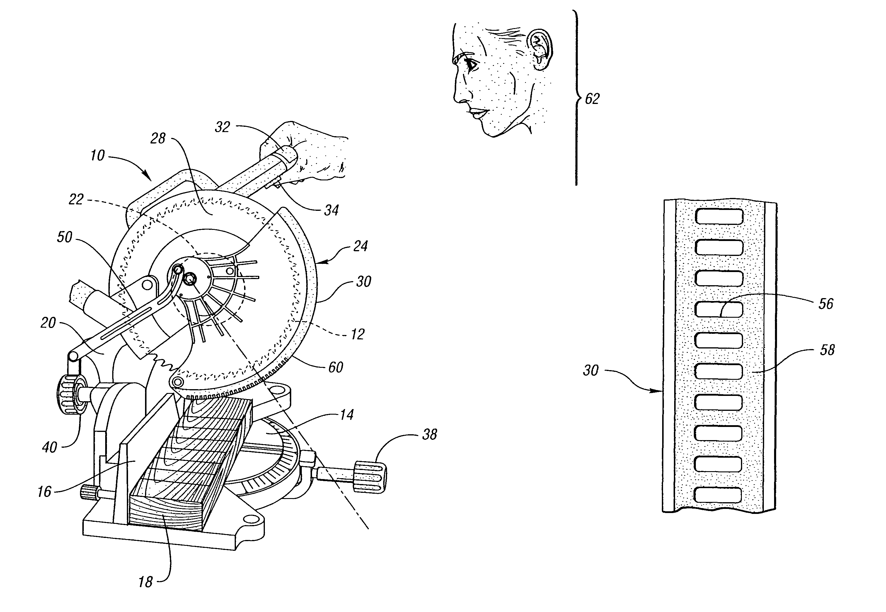
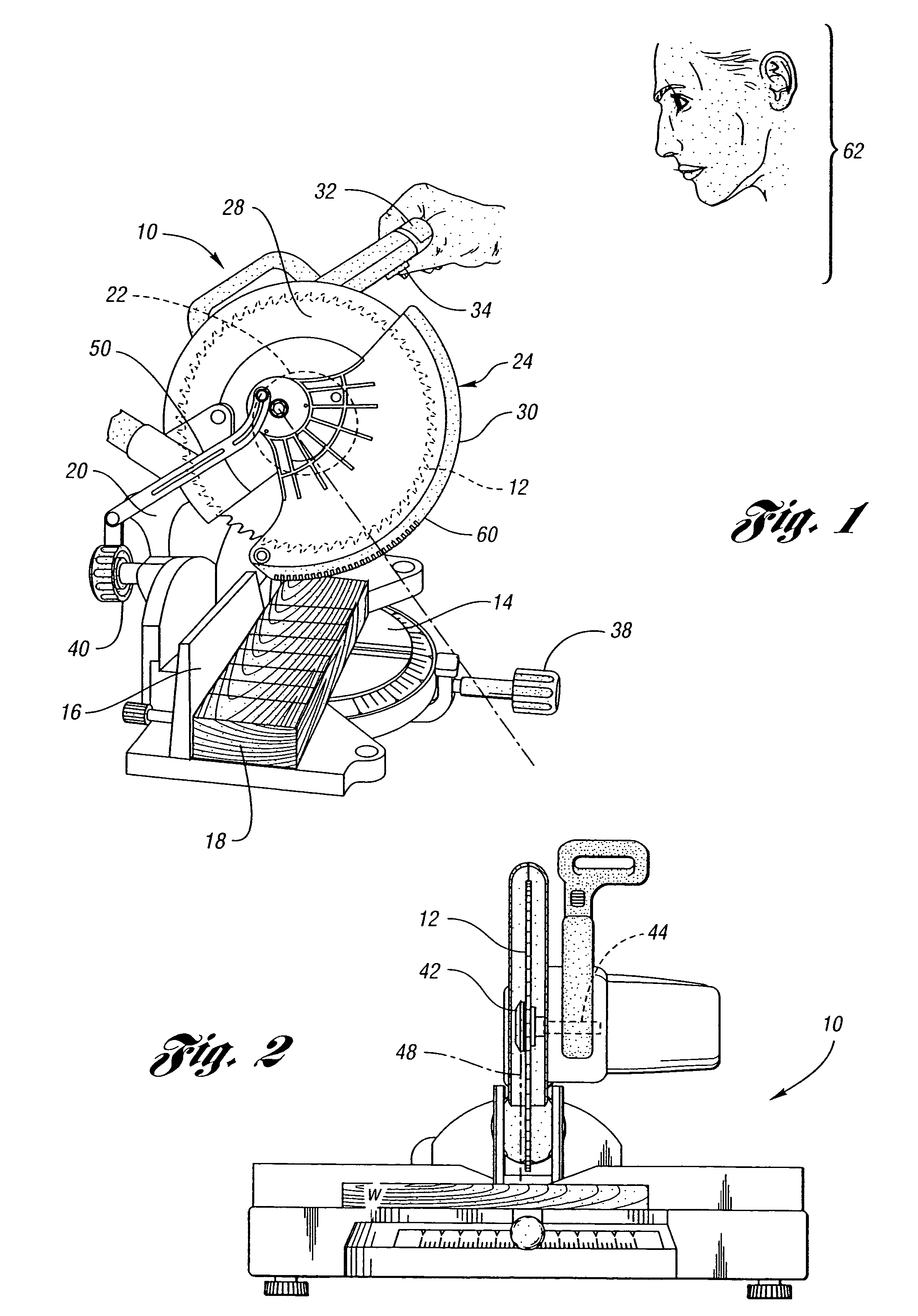
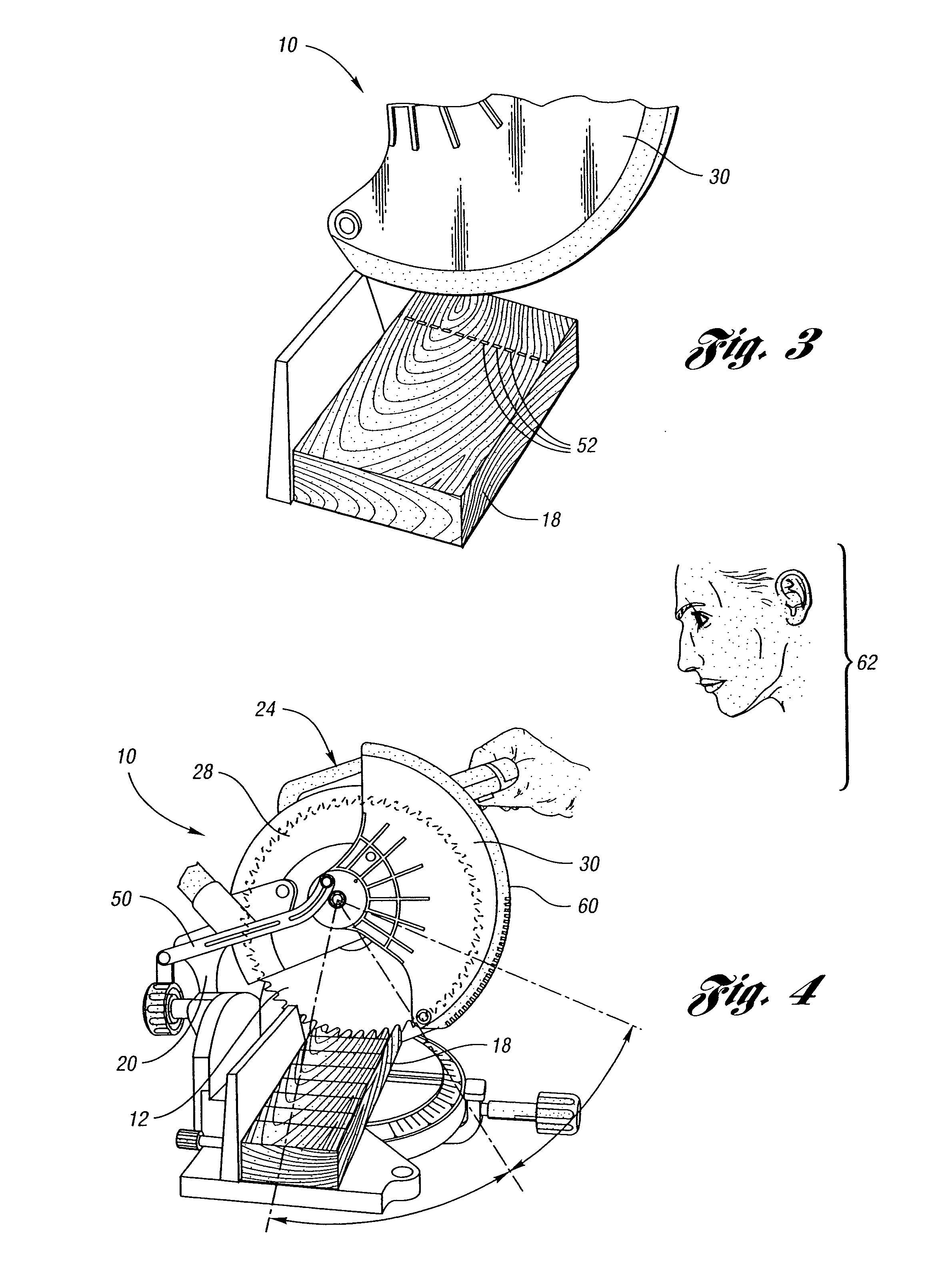
[0029]Referring now to FIG. 1, a miter saw 10 having a circular saw blade 12 is shown. The miter saw 10 also includes a base 14 and fence 16 against which a workpiece 18 is located when the workpiece 18 is cut by the miter saw 10. An arm 20 connects the motor assembly 22 that forms part of the saw head assembly, generally indicated by reference numeral 24. The saw head assembly 24 includes a circular saw blade 12 and also includes a fixed guard 28 and movable shield 30 as well as a handle 32 that includes the power switch 34.

[0030]The saw 10 shown in the illustrated embodiment is a compound miter saw having a miter angle adjustment mechanism 38 and a tilt adjustment mechanism 40. While the illustrated embodiment is of a compound miter saw, the invention is equally applicable to a simple miter saw, a sliding compound miter saw, or a chop saw. The saw head assembly 24 is pivotally connected to the arm 20 and includes a spring (not shown) for biasing the saw head assembly 24 out of en...


PUM

PropertyMeasurementUnit
precise anglesaaaaaaaaaa
speedaaaaaaaaaa
angleaaaaaaaaaa

Abstract

A table saw such as a chop saw, a miter saw, compound miter saw or a sliding compound miter saw that is provided with a laser arbor alignment system. An opaque shield or transparent shield having an opaque mask blocks the laser beam from being projected into a range of normal operator eye positions. One or more openings in the shield or opaque mask provide a sight line on a workpiece initially. As the saw is moved into engagement with the workpiece, the shield is pivoted away from the workpiece and a solid laser line is projected on the workpiece.

Description

[0001]This application is a continuation of U.S. Ser. No. 10 / 774,854, filed Feb. 9, 2004 now abandoned, which is a continuation of U.S. Ser. No. 09 / 860,898 filed May 18, 2001, now U.S. Pat. No. 6,755,107.BACKGROUND OF THE INVENTION[0002]1. Field of the Invention[0003]The present invention relates to a miter saw having a laser, or other light source, alignment system that uses a beam of light for positioning a saw blade.[0004]2. Background Art[0005]Miter saws are used to cut wood and other materials at precise angles. For example, miter saws are used to cut crown moldings, cove moldings, and other trim pieces and structural members at precise angles. Miter saws generally have a circular blade that is rotated at a high rate of speed to cut workpieces. The blade is guarded by a retractable blade guard that covers the saw blade but is retracted as the blade is brought into contact with a workpiece. The workpiece is generally retained on a supporting table that is adjustable and, in conj...

Claims


Application Information

Patent Timeline
Patent Type & Authority Patents(United States)
IPC IPC(8): B26D7/00B23D45/04B27B9/00B23D59/00B23Q11/06B23Q17/24B27B5/32B27G19/02
CPCB23D59/002B23D59/003B23Q11/06B27G19/02B23Q17/2404B27B5/32B23Q17/24Y10T83/7788Y10T83/828Y10T83/7697Y10T83/853Y10T83/8773Y10T83/839Y10T83/7734
Inventor PEOT, DAVID G.MINALGA, PHILIP F.HORNICK, GEORGE M.BUCK, WILLIAM C.KAISER, WILLIAM E.
Owner EASTWAY FAIR
Why Eureka
Try Eureka