Valve arrangement

a valve arrangement and valve technology, applied in the direction of service pipe systems, gas/liquid distribution and storage, water mains, etc., can solve the problems of affecting the supply of hydraulic fluid, and achieve the effect of simple design, simple design and simple connection design

Active Publication Date: 2008-07-15
DANFOSS PAUER SOLYUSHENS APS
View PDF12 Cites 28 Cited by
  • Summary
  • Abstract
  • Description
  • Claims
  • Application Information

AI Technical Summary

Benefits of technology

[0010]In the case of an error in a control valve, this embodiment makes it possible to place the complete valve arrangement is a safe state, for example in that the safety valve blocks the supply of pressurised hydraulic fluid from the high-pressure connection to the control valves. This safety function is integrated in the valve arrangement, that is, a blocking of the valve arrangement does not require that firstly the error in the control valves is detected, and then transmitted via a cable to an external monitoring device, which again sends a signal back to the safety valve. On the contrary, the complete safety is integrated in the valve arrangement. Thus, the valve arrangement can initially be configured in the manner, which is desired for the connected consumer. Depending on the number of consumers to be connected, more or less modules can be combined. Usually, module housings are connected laterally by means of flanges. However, this is not necessarily required. Also embodiments, in which hydraulic pipes exist between modules, can be imagined. Such an embodiment is still considered to be a “component group”. The complete valve arrangement with all control valve modules and the safety valve module can then be tested, not only with regard to operability, but also with regard to meeting the safety requirements. This test can be made by the manufacturer, so that in a manner of speaking the valve arrangement is autonomic. Thus, such a valve arrangement is completely independent of application. In principle, it does not matter at all, which components exist around the valve group, and also it does not matter, whether a crane, a wo

Problems solved by technology

This safety valve interrupts the supply of hydraulic f

Method used


Image

  • Valve arrangement
  • Valve arrangement
  • Valve arrangement

Examples


Embodiment Construction

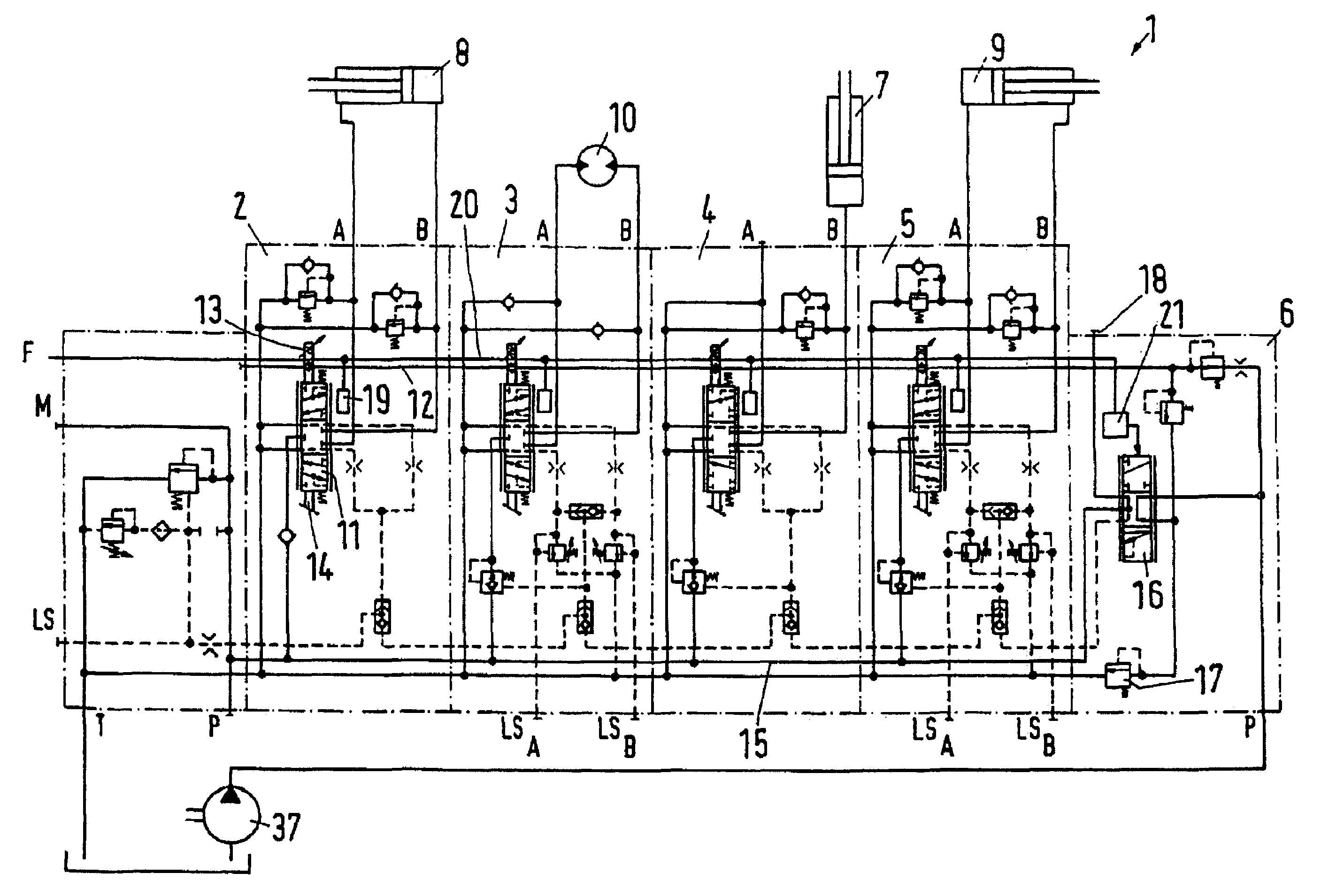
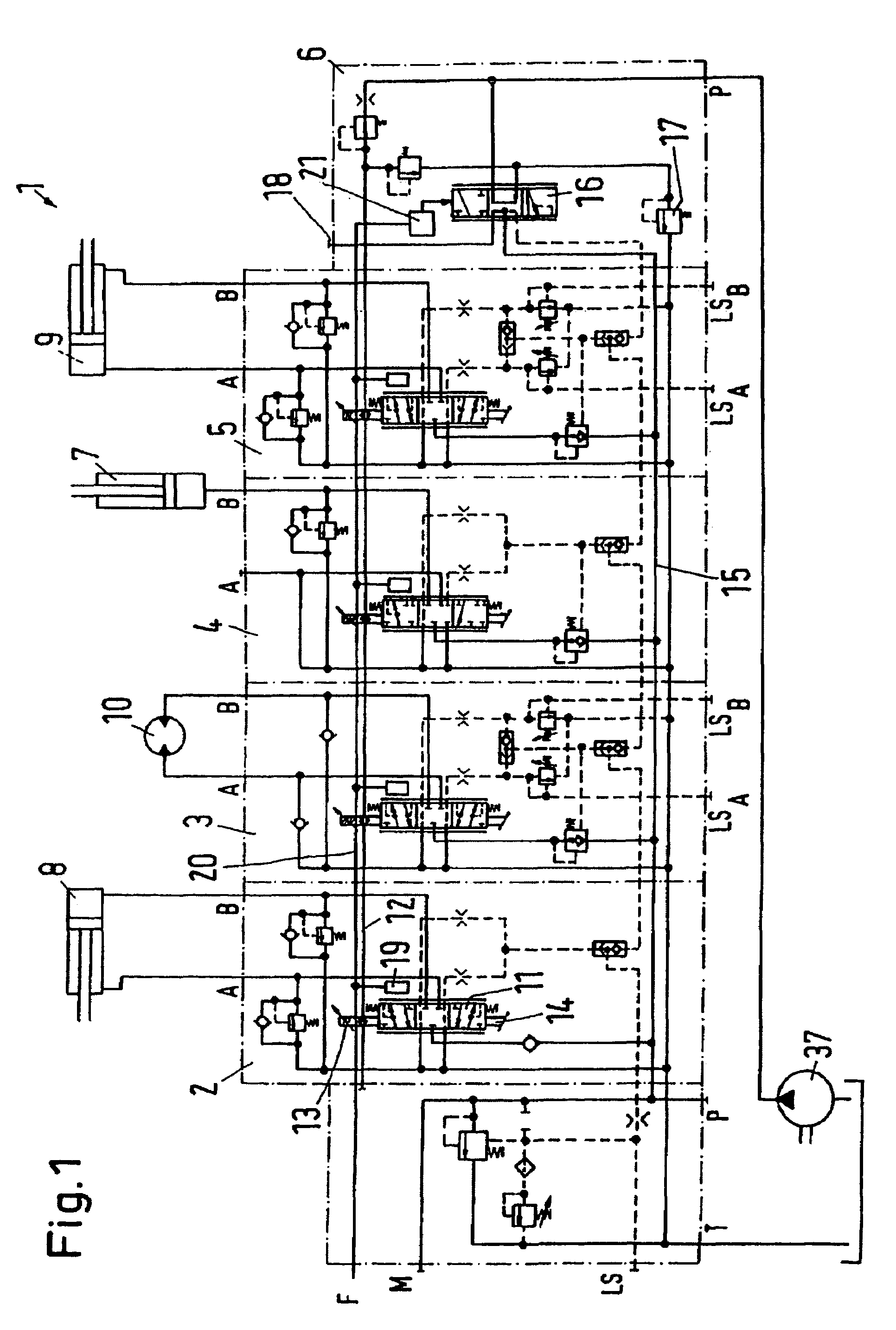
[0026]A valve arrangement 1 has a high-pressure connection P, a low-pressure connection T; several control valves 2 to 5 and a safety valve 6. Each control valve has two working connections A, B, to which hydraulic consumers are connected. The hydraulic consumers can have different designs. Examples are a single-acting cylinder 7, double-acting cylinders 8, 9 or a rotary motor 10. Of course, more than the four control valves 2 to 5 may be provided. The number of control valves 2 to 5 depends on the number of desired hydraulic functions.

[0027]All control valves 2 to 5 are proportional valves, having a valve element 11, which is supplied with a pilot pressure via a pilot pressure pipe 12. The pilot pressure of the pilot pressure pipe 12 is then led on to the valve element 11 via a solenoid valve arrangement 13 so that the valve element is displaced in one direction or the other. In many cases, the valve element 11 is a valve slide.

[0028]The valve element 11 can also be displaced by a ...


PUM


Abstract

The invention concerns a valve arrangement (1) with a high-pressure connection (P), a low-pressure connection (T), at least one control valve (2 to 5), which is accommodated in a control valve module and has at least one working connection (A, B) for a hydraulic consumer (7 to 10), and a safety valve (6), which is accommodated in a safety valve module, and which releases or blocks a passage between the high-pressure connection (P) and the control valves (2 to 5), the control valve module (2 to 5) and the safety valve module (6) being connected to one component group. It is endeavoured to provide a valve arrangement with a high safety level. For this purpose, it is ensured that each control valve (2 to 5, 2′ to 5′) has an error detection device (19), that the safety valve module (6) has a safety switch device (21) and that the component group has a connection (20) between the safety switch device (21) and the error detection device (19).

Description

CROSS-REFERENCE TO RELATED APPLICATIONS[0001]Applicant hereby claims foreign priority benefits under U.S.C. § 119 from German Patent Application No. 10 2004 028 437.7, filed on Jun. 14, 2004, the contents of which are incorporated by reference herein.FIELD OF THE INVENTION[0002]The invention concerns a valve arrangement and, more specifically, to a safety valve therefor.BACKGROUND OF THE INVENTION[0003]Certain valve arrangements are known from the company brochure Sauer-Danfoss “PVSK module with integrated diverter valve and P-disconned function”, edition November 2002.[0004]With machines and devices performing hydraulic functions, usually several consumers are present, each being controlled by a control valve. For example, in connection with a crane, there are several cylinders, which lift different sections of a jib, a rotary motor, with which the jib can be turned, and, if required, a further hydraulic function, with which a grab mounted at the end of the jib can be activated. Si...

Claims


Application Information

Patent Timeline
IPC IPC(8): F15B13/06F15B20/00F16K37/00
CPCF15B13/0867F15B20/008F15B2211/8755F15B2211/87F15B2211/8636Y10T137/87885Y10T137/8242Y10T137/8175
Inventor HJORTH, HENRIKVESTER, JENS
Owner DANFOSS PAUER SOLYUSHENS APS
Why Eureka
Try Eureka