Reinforcing bar binding machine

a technology of reinforcing bars and binding machines, which is applied in the directions of bundling machine details, applications, bundling articles, etc., can solve the problems of reducing the operation speed weakening the operation force of the mechanism portion, and becoming impossible to exhibit the original performance of the binding machin

Active Publication Date: 2008-07-15
MAX CO LTD
View PDF7 Cites 18 Cited by
  • Summary
  • Abstract
  • Description
  • Claims
  • Application Information

AI Technical Summary

Benefits of technology

[0004]Therefore, one or more embodiments of the present invention provide a reinforcing bar binding machine in which no failure in operation is caused even when the reinforcing bar binding machine is used in a cold environment.
[0008]According to one or more embodiments of the present invention, when a warming-up mode is selected in a reinforcing bar binding machine, a warming-up operation, in which a binding wire cutting mechanism is driven by a predetermined times, is carried out. Therefore, even in an environment of low temperature, it is possible to evade the occurrence of a case in which it is difficult to start a reinforcing bar binding machine due to an increase in the viscosity of lubricant. Accordingly, it is possible to solve a problem in which the performance of the reinforcing bar binding machine is deteriorated when it is used in a cold environment. When not a usual operation cycle of the reinforcing bar binding machine but only a binding wire cutting operation is carried out, the binding wire is not wasted.

Problems solved by technology

Accordingly, it becomes impossible to exhibit the original performance of the binding machine.
Accordingly, in addition to the increase in the viscosity of grease, due to the reduction in the battery voltage, an operation speed of a mechanism portion is decreased and further an operating force of the mechanism portion becomes weak.
Consequently, there is a possibility that failure in operation is caused and further it becomes impossible to start the binding machine.

Method used


Image

  • Reinforcing bar binding machine
  • Reinforcing bar binding machine
  • Reinforcing bar binding machine

Examples


Embodiment Construction

[0018]Referring to the drawings, an embodiment of the present invention will be explained below.

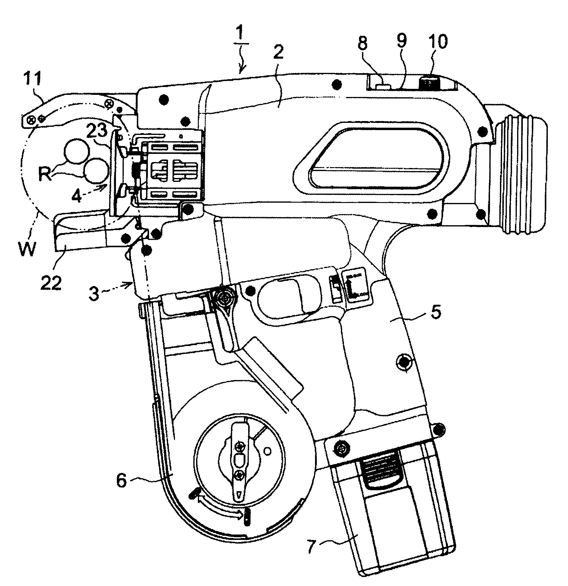
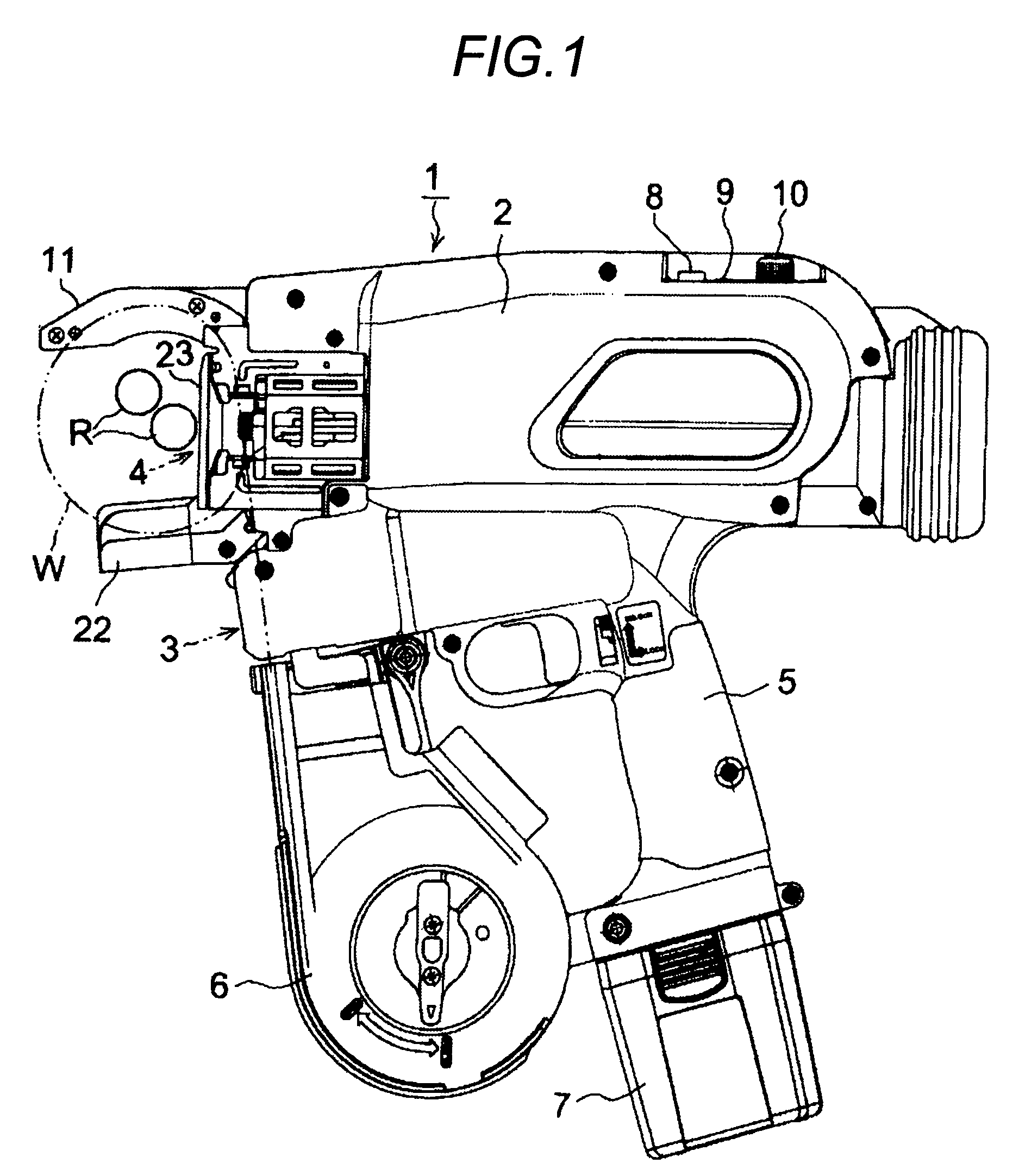
[0019]FIG. 1 is a view showing an electric type reinforcing bar binding machine 1. A binding wire feed mechanism 3 and a binding wire twist mechanism 4 are incorporated into a housing 2. In a magazine 6 arranged in the front of a grip portion 5 of the housing 2, a binding wire reel (not shown) is charged. To an end portion of the grip portion 5, a battery pack 7, into which NiMH battery is incorporated, is attached. Through an electric power circuit board (not shown), the battery pack 7 supplies electric power to a feed motor of the binding wire feed mechanism 3 and a feed motor of the binding wire twist mechanism 4.

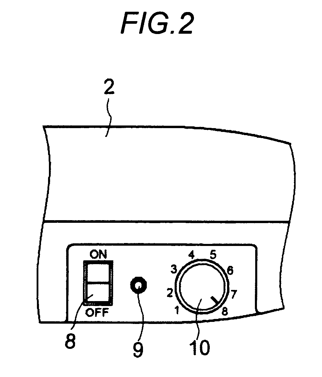
[0020]As shown in FIGS. 1 and 2, there are provided an electric power source switch 8, a warning detection LED 9 and a twist torque adjustment dial 10 on an upper face at the rear of the reinforcing bar binding machine 1. In the housing 2, a buzzer (not shown) for warning rela...


PUM

PropertyMeasurementUnit
temperatureaaaaaaaaaa
viscosityaaaaaaaaaa
sliding resistanceaaaaaaaaaa

Abstract

A reinforcing bar binding machine is provided with a control unit operated in such a manner that at the time of turning on an electric power source switch, a setting position of a motor drive adjustment dial and a state of a trigger lever are read, and when the motor drive adjustment dial is at a specific setting position and when the trigger lever is turned on, a binding wire cutting mechanism is driven by a predetermined number of times for warming up the binding wire cutting mechanism. When the warming-up operation is carried out in a cold environment, it is possible to reduce the viscosity of grease coated on a mechanism portion. Therefore, it is possible to lower a viscosity of grease applied on a mechanical portion and conduct a reinforcing bar binding work without wasting a binding wire in the same manner as that in a warm environment.

Description

TECHNICAL FIELD[0001]The present invention is related to a reinforcing bar binding machine. More particularly, the present invention is related to a reinforcing bar binding machine having a warming-up function so as to prevent the occurrence of failure in operation in a low temperature environment.BACKGROUND ART[0002]It is a matter of general knowledge to appropriately use lubricant for a rotary shaft, a sliding face of a piston and a frictional face of a gear or a cam in a power tool such as an electric tool or a pneumatic tool. Concerning this matter, for example, refer to JP-A-2003-136435. In the case of lubrication of a rotary shaft or a sliding member, the sliding speed of which is relatively low, to which a heavy load is given, provided in a binding wire twisting mechanism of a reinforcing bar binding machine, grease of higher viscosity is used.[0003]In the case where the reinforcing bar binding machine is used outside where a temperature is very low, the viscosity of grease i...

Claims


Application Information

Patent Timeline
Patent Type & Authority Patents(United States)
IPC IPC(8): B65B13/28
CPCE04G21/122E04G21/123
Inventor KUSAKARI, ICHIRONAGAOKA, TAKAHIROITAGAKI, OSAMUMATSUOKA, ATSUSHI
Owner MAX CO LTD
Why Eureka
Try Eureka