

Device for welding plastic tubes
a technology for plastic tubes and devices, applied in the direction of instruments, photosensitive materials, other domestic objects, etc., can solve the problems of small operating window, intrinsic weakness or high implementation cost of weld removal and preventing fluid from entering the weld site, and the difficulty of welding liquid filled tubes
- Summary
- Abstract
- Description
- Claims
- Application Information
AI Technical Summary
Benefits of technology
Problems solved by technology
Method used
Image

Examples
Embodiment Construction
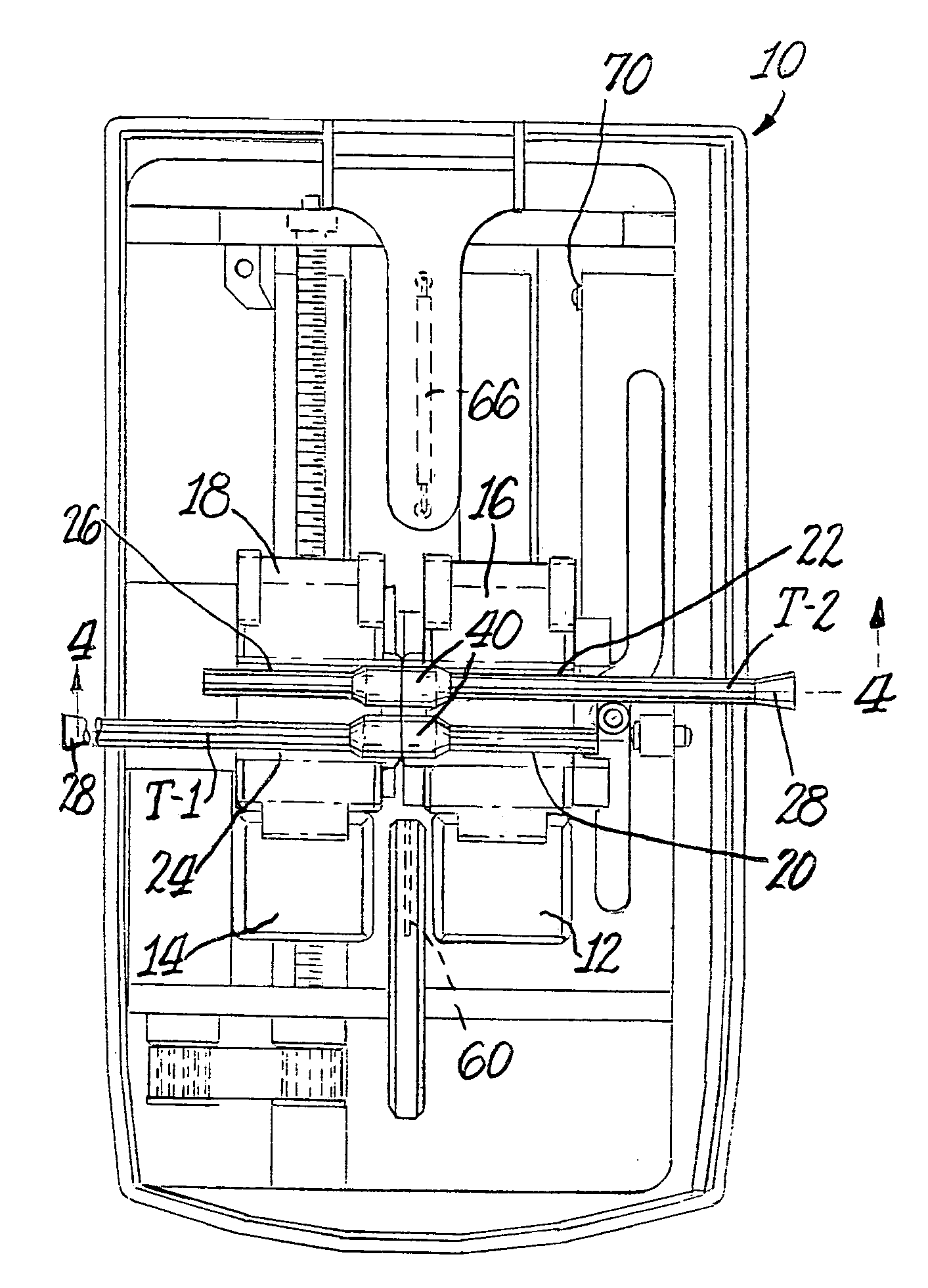
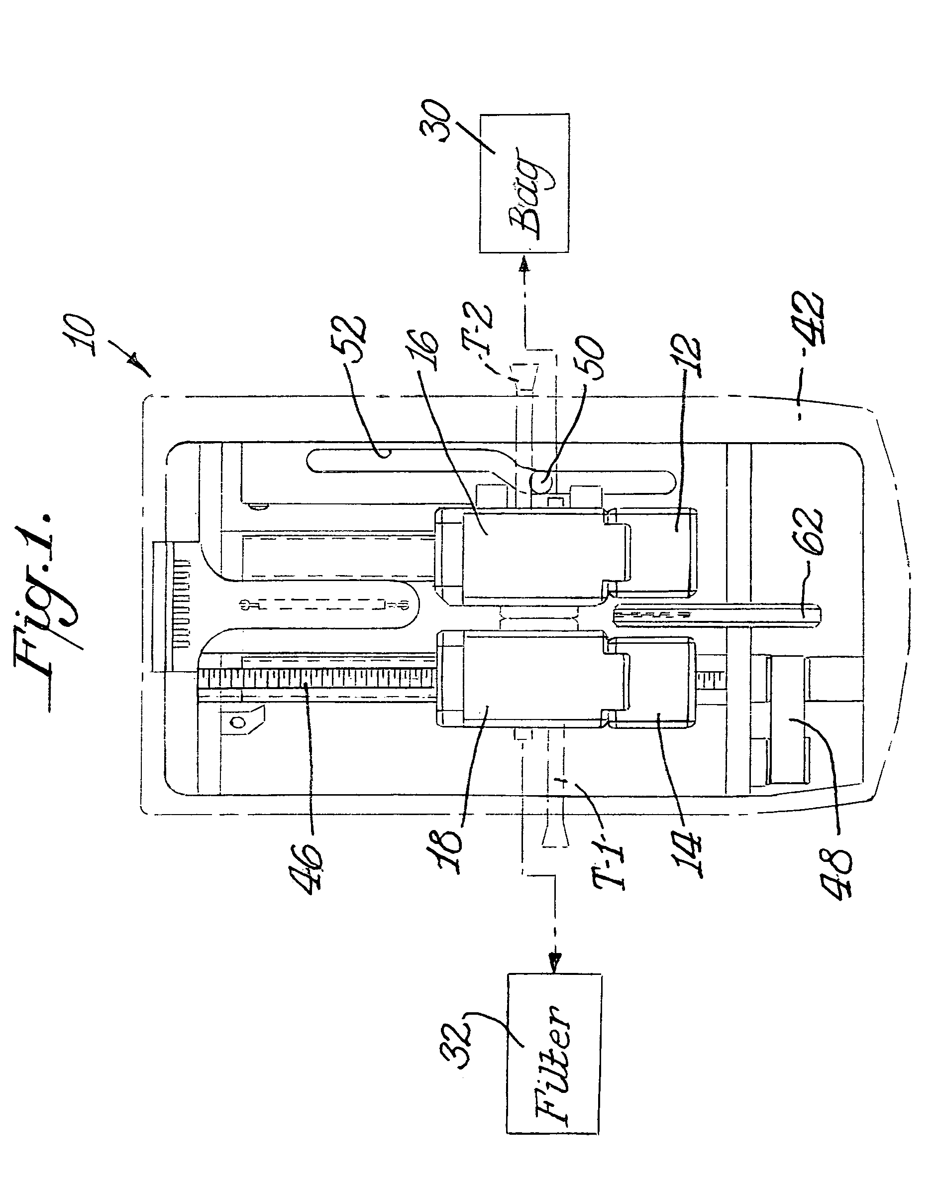
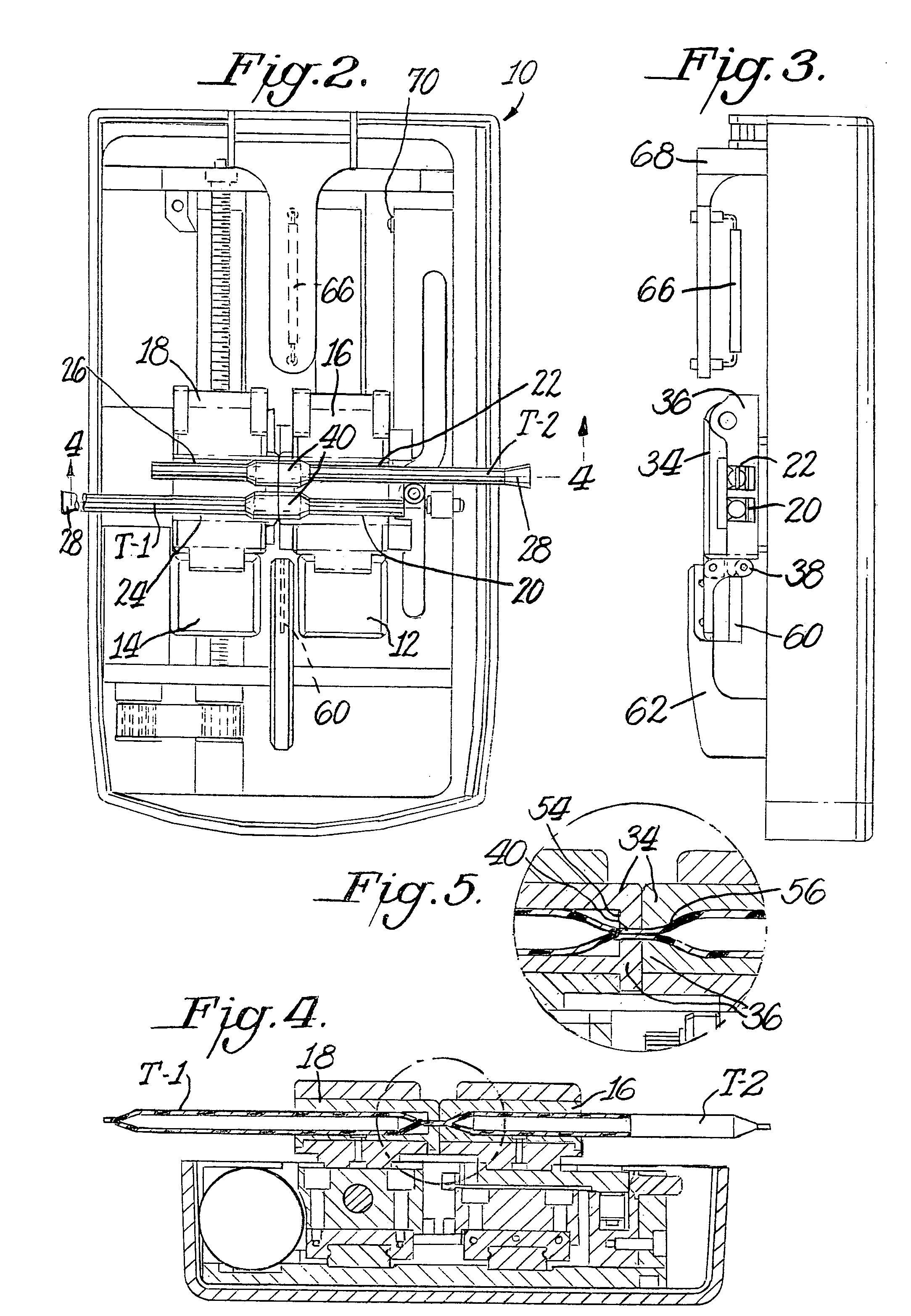
[0038]The present invention, in its preferred embodiment, involves techniques for accomplishing a sterile welding of plastic tubes, particularly wherein at least one of the plastic tubes might contain a fluid. The sterile welding is accomplished without the use of a conventional heated wafer. More particularly, in the preferred embodiment, the plastic tubes are placed in parallel orientation with respect to each other in the tube holding areas of side by side tube holders at a loading station. The tube holders include clamps which compress the tubes to create flattened areas free of any fluid. One of the tube holders is then laterally shifted in a stripping station while the clamps are in their engaged position to increase the fluid free area. The tube holders are then moved longitudinally to a cutting station where the tubes are cut by a cold cutting blade to create four cut or stub ends in the fluid free areas so that each stub end is also free of fluid. The tube holders are again...
PUM
| Property | Measurement | Unit |
|---|---|---|
| time | aaaaa | aaaaa |
| diameter | aaaaa | aaaaa |
| diameter | aaaaa | aaaaa |
Abstract
Description
Claims
Application Information